Semiconductor ultrafine particles, fluorescent material, and light-emitting device

a technology of semiconductors and ultrafine particles, which is applied in the direction of mercury compounds, lighting and heating apparatuses, instruments, etc., can solve the problems of unstable ultrafine particles produced in ph-reduced solutions, achieving higher fluorescence quantum yield, and poor light resistance, etc., to achieve excellent light resistance, temporal stability, and brightness. good

Inactive Publication Date: 2007-04-05
NAT INST OF ADVANCED IND SCI & TECH
View PDF2 Cites 7 Cited by
  • Summary
  • Abstract
  • Description
  • Claims
  • Application Information

AI Technical Summary

Benefits of technology

[0015] The present invention was made in view of the problems of the prior art, and the principal object is to provide a novel fluorescent material that has better brightness than

Problems solved by technology

This phenomenon is a major obstacle to achieving higher brightness through the use of rare earth ions or transition metal ions.
Ultrafine particles produced by this procedure are dispersed in water and are stable for a while, however, they are inferior in the fluorescence quantum yield to the ultrafine particles produced in a non-aqueous solvent described below.
However, ultrafine particles produced in a pH-reduced solution are unstable, and fluorescence quantum yield decreases to half or less in air in about 7 days.
Since etching ultrafine particles by irradiation with light requires about five days and the particle size distribution of the produced particles expands, the width of the emission spectrum also adversely enlarges.
However, this method disadvantageously requires expensive and complicated experimental equipment, and special considerations to ensure safety.
Another drawback is that in most cases ultrafine particles thus produced remain stable in water for only about a few hours.
Therefore, these drawbacks are major factors impeding the practical application of particles produced in a nonaqueous solvent.
Thus, surface-coated semiconductor ultrafine particles emi

Method used


Image

  • Semiconductor ultrafine particles, fluorescent material, and light-emitting device
  • Semiconductor ultrafine particles, fluorescent material, and light-emitting device
  • Semiconductor ultrafine particles, fluorescent material, and light-emitting device

Examples


example 1

[0115] Group II-VI semiconductor cadmium telluride ultrafine particles were produced according to the following process obtained by improving the method described in Gao, et al., Journal of Physical Chemistry, B, vol. 102, p. 8360 (1998).

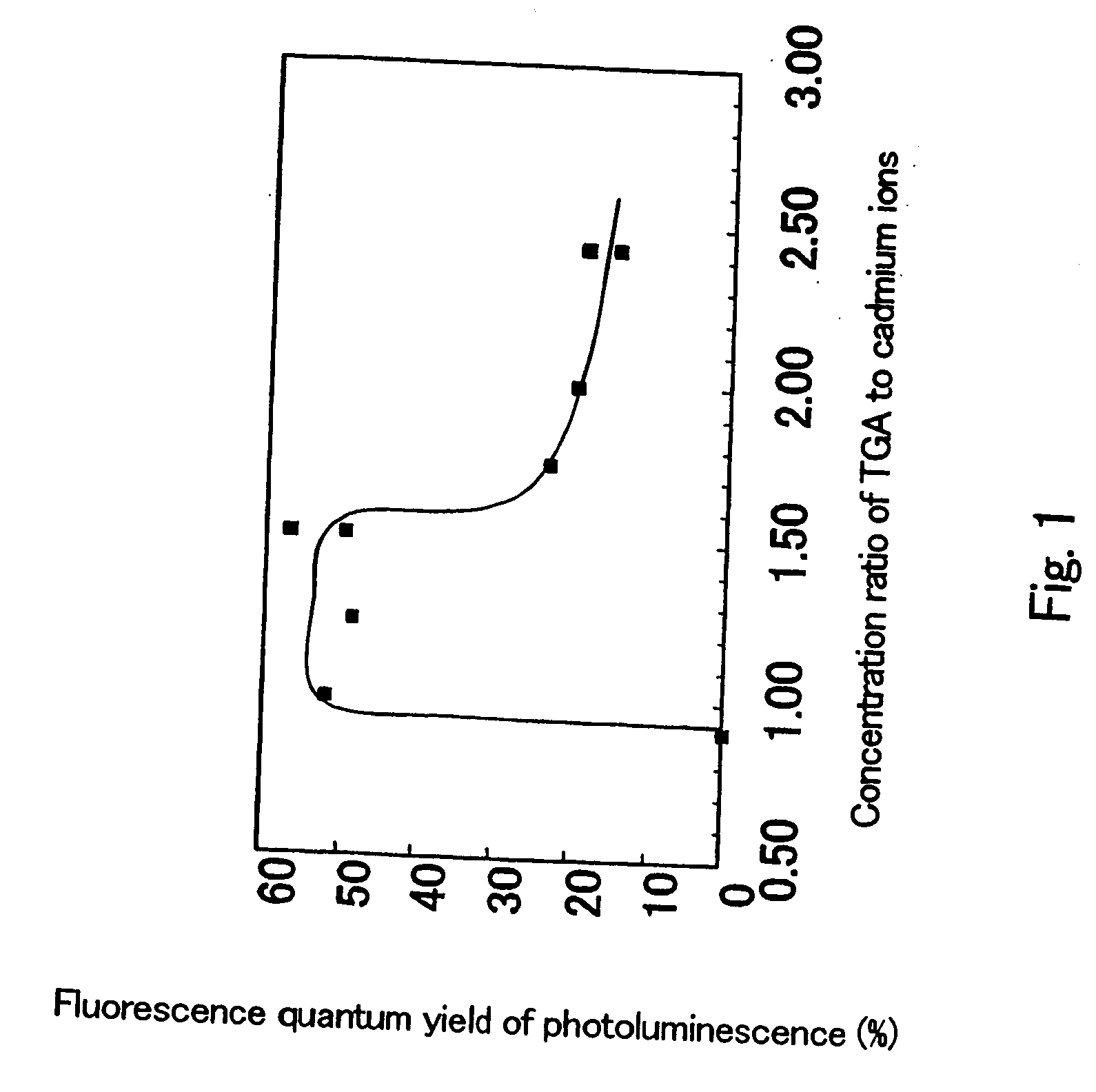
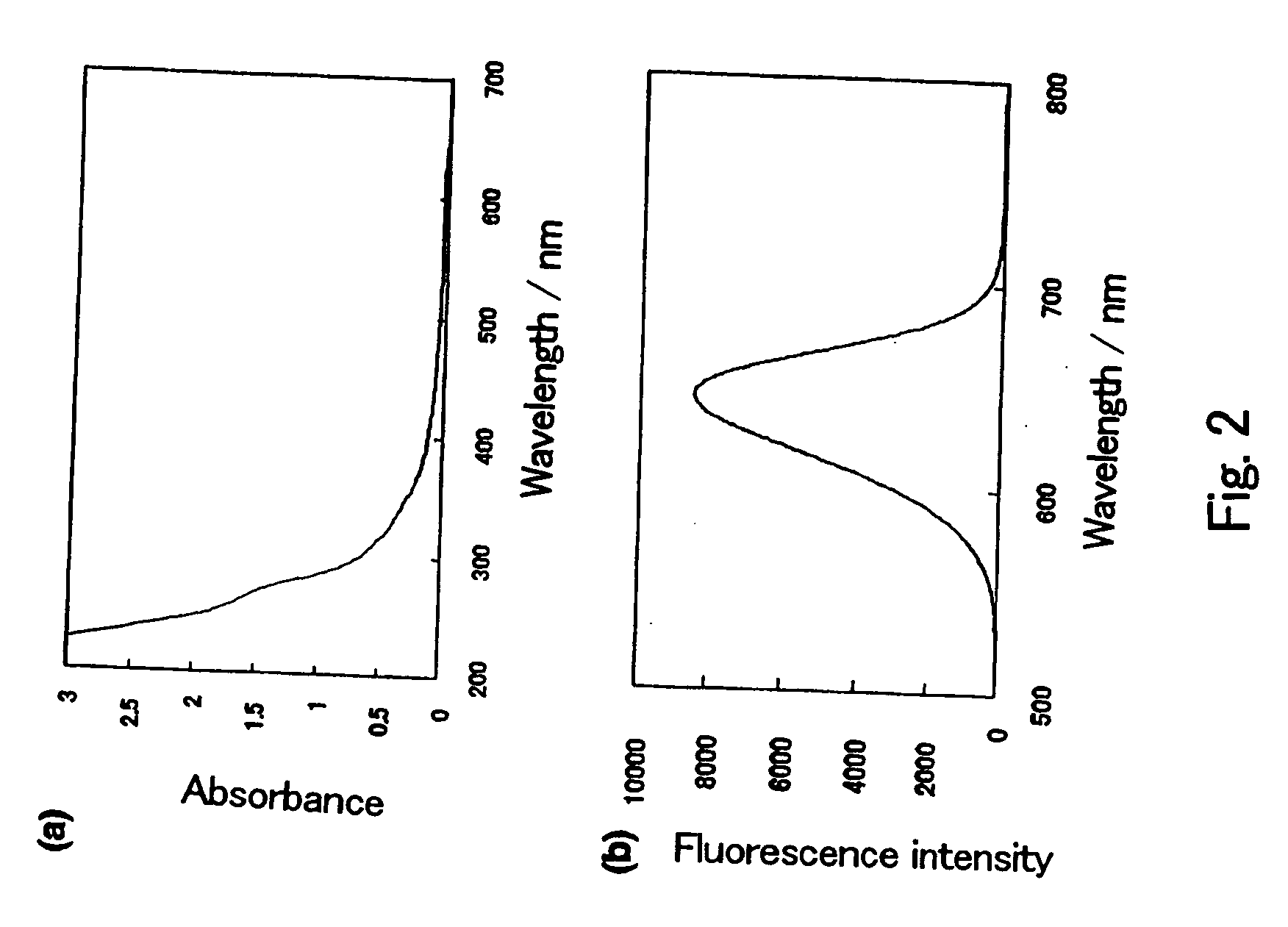
[0116] More specifically, in a Clean Room (10000 class or less), hydrogen telluride gas was added to an aqueous cadmium perchlorate solution (concentration of 0.013 mol / L) while vigoursly stirring in a round bottom flask charged with an argon gas, and the aqueous cadmium perchlorate solution has apH adjusted to 11.4 and comprises thioglycolic acid (HOOCCH2SH) (TGA) as a surfactant. The resulting mixture was further stirred, yielding a dispersion of cadmium telluride ultrafine particles. The dispersion of ultrafine particles thus obtained emitted red light when irradiated by ultraviolet light. Ultrapure water (produced by a pure water producing machine, Milli-Q synthesis, manufactured by Nippon Millipore Corporation: Specific resistance; 18 MΩ·cm or...

example 2

[0122] 3 g of aminopropyltrimethoxy silane and 28 g of methanol were sufficiently stirred, and 10 ml of the mixture was extracted and put into a petri dish made of a fluororesin with a diameter of 5 cm.

[0123] A small stirring bar was placed in this petri dish, and 2.8 ml of water was then put therein. The mixture was stirred while covering the dish from the top to prevent the entry of dust, and hydrolysis and subsequent dehydration condensation polymerization were allowed to proceed according to reaction formula.

H2N—(CH2)3—Si—(OCH3)3+3H2O→H2N—(CH2)3—Si—(OH)3+3CH3OH

[0124] When the viscosity of the solution reached about 1000 centipoise after about 12 hours passed at a temperature of 23° C. and humidity of 60%, 1.2 ml of the dispersion of cadmium telluride ultrafine particles which emitted the red light of Example 1 (X=1.50, and immediately after production) was put in the solution, and the result was further stirred for 10 minutes, yielding a glass precursor solution. The viscosity ...

example 3

[0127] The glass of Example 2 was heated at 100° C. under an atmosphere of argon for two hours. At this time, the rate of the rise or drop in temperature was set to be 0.5° C. / minute to prevent the formation of cracks in the glass. This heat treatment caused the weight to decrease by about 5%. The fluorescence quantum yield of the ultrafine particles in the glass of Example 2 was retained in the ultrafine particles in the obtained cured glass.

[0128] The hardness of the heat-treated glass was measured with a hardness tester (manufactured by Akashi, Microvickers Hardness Tester MVK-E), and a Vickers hardness of about 50 (490 megapascals in the International System of Units). Since the glass before the heat treatment was too soft and no indentation were formed, the hardness was not able to be measured. As described above, the heat treatment permitted the dehydration condensation reaction to proceed, thereby improving the quality of the glass.

[0129] It was determined that this heat tr...


PUM

PropertyMeasurementUnit
Temperatureaaaaaaaaaa
Fractionaaaaaaaaaa

Abstract

The present invention provides a novel fluorescent material which has a luminance higher than that of the conventional rare earth ion-dispersed fluorescent materials and is excellent in light resistance and long-term stability, and also an optical device, such as a high-luminance display panel or lighting equipment, which uses such a fluorescent material. Semiconductor ultrafine particles are characterized by maintaining 50% or more fluorescence quantum yield of photoluminescence when they are kept dispersed in water at 10° C. to 20° C. in air for 5 days. The fluorescent material is obtained by dispersing such semiconductor ultrafine particles in a glass matrix using a sol-gel process.

Description

TECHNICAL FIELD [0001] The present invention relates to semiconductor ultrafine particles, a fluorescent material, and a manufacturing process therefor, and a lighting device and display device using the fluorescent material. BACKGROUND OF THE INVENTION [0002] In the ongoing information technology revolution, display elements and assemblies thereof, i.e., monitors such as displays, play an important role as interfaces between people and various types of equipment. Such display elements are faced with continuous demands for higher brightness and higher resolution, and must also be as thin and lightweight as possible. Fluorescent materials with high fluorescence quantum yield and brightness are indispensable for meeting such requirements. Moreover, such fluorescent materials are also used in a wide variety of applications for lighting materials. Therefore, research has been conducted to develop such fluorescent materials for about 100 years, starting in the beginning of the 20th centu...

Claims


Application Information

Patent Timeline
IPC IPC(8): C09K11/08B82Y20/00G02F1/13357C01B19/04C09K11/02C09K11/88F21V8/00F21Y101/02G02F1/13H01J11/02H01J61/44
CPCC09K11/02C09K11/883G02F1/133617
Inventor MURASE, NORIOLI, CHUNLIANG
Owner NAT INST OF ADVANCED IND SCI & TECH
Why Eureka
Try Eureka