The equipment housed within data centers can be very valuable, but the data stored by that equipment is potentially of much greater value, as is the cost of
downtime should the equipment fail.
Tenants can be expected to claim substantial damages if those objectives are not met.
However, the more access takes place, the more difficult it becomes to maintain a closed environment in which temperature,
humidity and ingress of dust or other contaminants can be controlled.
For example, to achieve a
clean environment IP (ingress protection) rating under British and European standards, a sealed filtered
system is required which is difficult when the sealed system is an entire room.
Also, a multi-tenant facility also increases the chances of accidental damage to equipment, such as
impact damage or
spillage of liquids.
However, in recent years, some operators have omitted
gas protection due to the high
capital cost of the system and the high cost of recharging the system once discharged.
Many gases are also environmentally unsound.
For example, relatively small but sudden fluctuations from the recommended
operating temperature (e.g. at a rate of temperature change of as little as 10° C. per hour) can cause
thermal shock and damage delicate circuits.
However, the dominant challenge in environmental control of the technical space is the generation of heat by the
electronic equipment housed within.
New designs of electronic equipment which are more compact than previous models tend to have
higher power consumption and therefore a greater
heat output.
So, while racks or cabinets can in theory be filled with such
high density equipment, in reality, overheating may occur in that event.
Servers present a considerably greater challenge in this respect than other equipment apt to be rack-mounted, such as UPS units.
This presents another challenge in terms of inadequate power supply.
Those designing cooling systems for data environments are faced with not just the problem of ever greater
cooling load requirements, but with predicting the size of the load to be allowed for at any given point of time.
New category cables such as ‘Cat 6’ are larger in
diameter than those of earlier generations, which both restricts
airflow within the rack and adds to the total rack weight.
The power supplies, often ‘hot pluggable’, add to the device weight and therefore to the overall rack weight.
The risk of overheating means that cabinets are very often left unfilled: they are not fully populated with servers or other equipment, meaning that some available levels remain unused.
This is to the detriment of efficient space utilization within the
data center and, ultimately, increases the cost of housing each
server because fewer servers or fewer tenants share the infrastructure costs of the
data center.
Such cables are relatively vulnerable to damage, as may for example be caused by maintenance engineers walking on exposed cables when the floor panels are lifted.
This ultimately costs money by loss of potential revenue generation.
However, the alternative of
air conditioning vents positioned in the ceiling or in walls close to the ceiling, as commonly found in offices, is not suitable for a data center.
Unsurprisingly, the energy demands associated with such an approach represent a significant cost factor.
Also, the cooling of individual servers relies heavily upon their internal fans and there may be no attempt to ensure that each server receives its necessary share of conditioned air.
So, for example, a server might receive inadequate cooling because adjacent servers nearer the air intake take a disproportionate amount of conditioned air.
Also, if a server fan should fail, that server will almost inevitably overheat.
Assuming initial design is correct, a lack of static pressure may arise from poorly-managed
floor openings and / or from close-coupled rack cabinets with additional fans.
Specifically,
cut-outs for cable entry below cabinets and elsewhere within the room, together with excessive perforated floor panels or grilles, causes overcooling, loss of static pressure and wasted capacity.
High-pressure areas of the floor are overcooled while low-pressure areas overheat because a loss of static pressure reduces the size of a plume and hence the volume of room space that that plume is able to cool.
However, in practice, poorly-fitting floor panels or, more usually, floor panels that have been lifted and replaced badly can result in substantial leakage of cooled
airflow from the floor void.
If the floor void is used for containing cabling then engineers installing cables typically remove a complete row of floor panels and / or stringers rather than leave occasional panels (typically every fifth panel) in place to keep the floor ‘locked-in’, with the result that the panels shift across the whole floor in a process called ‘fish-tailing’, causing gaps to open up.
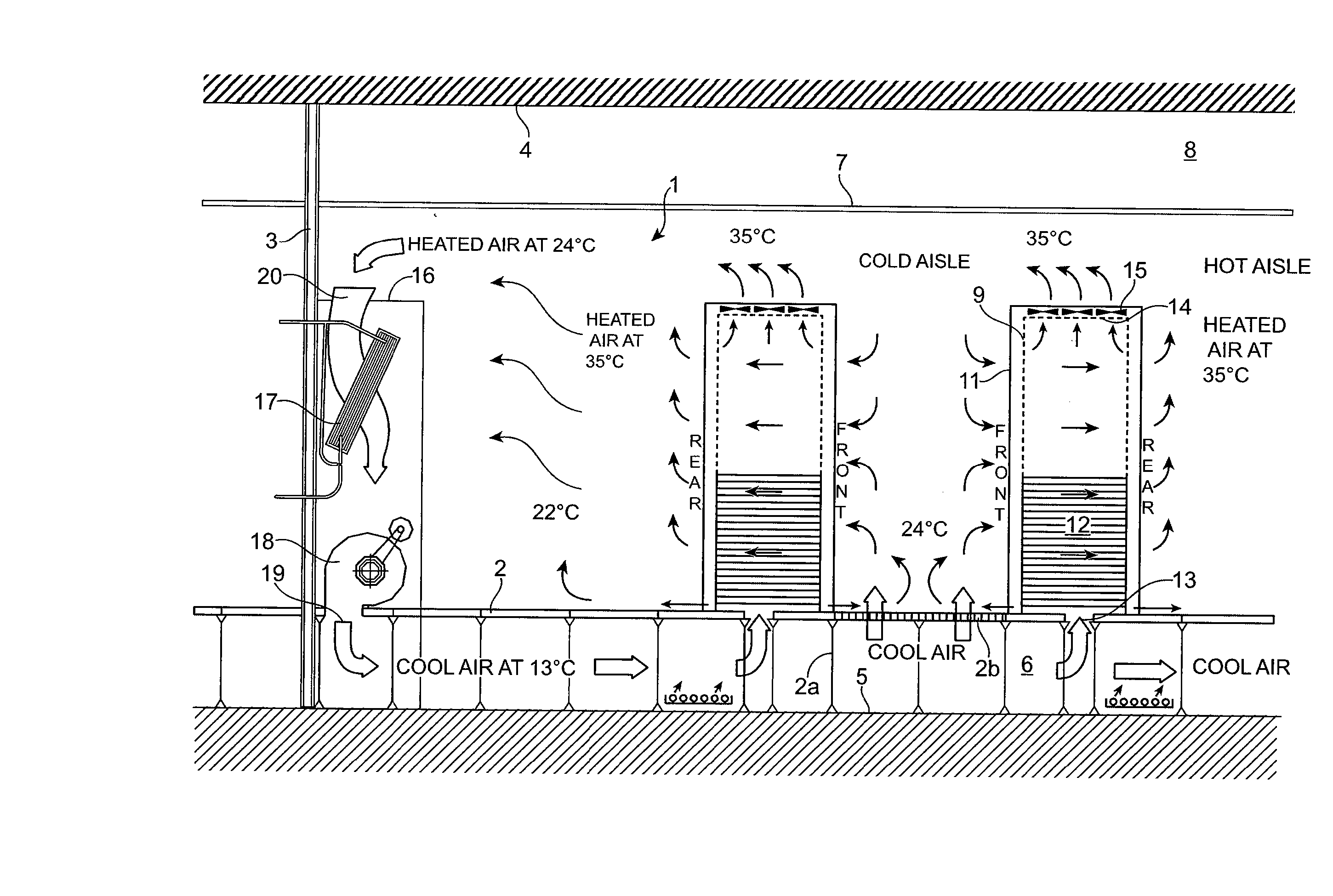
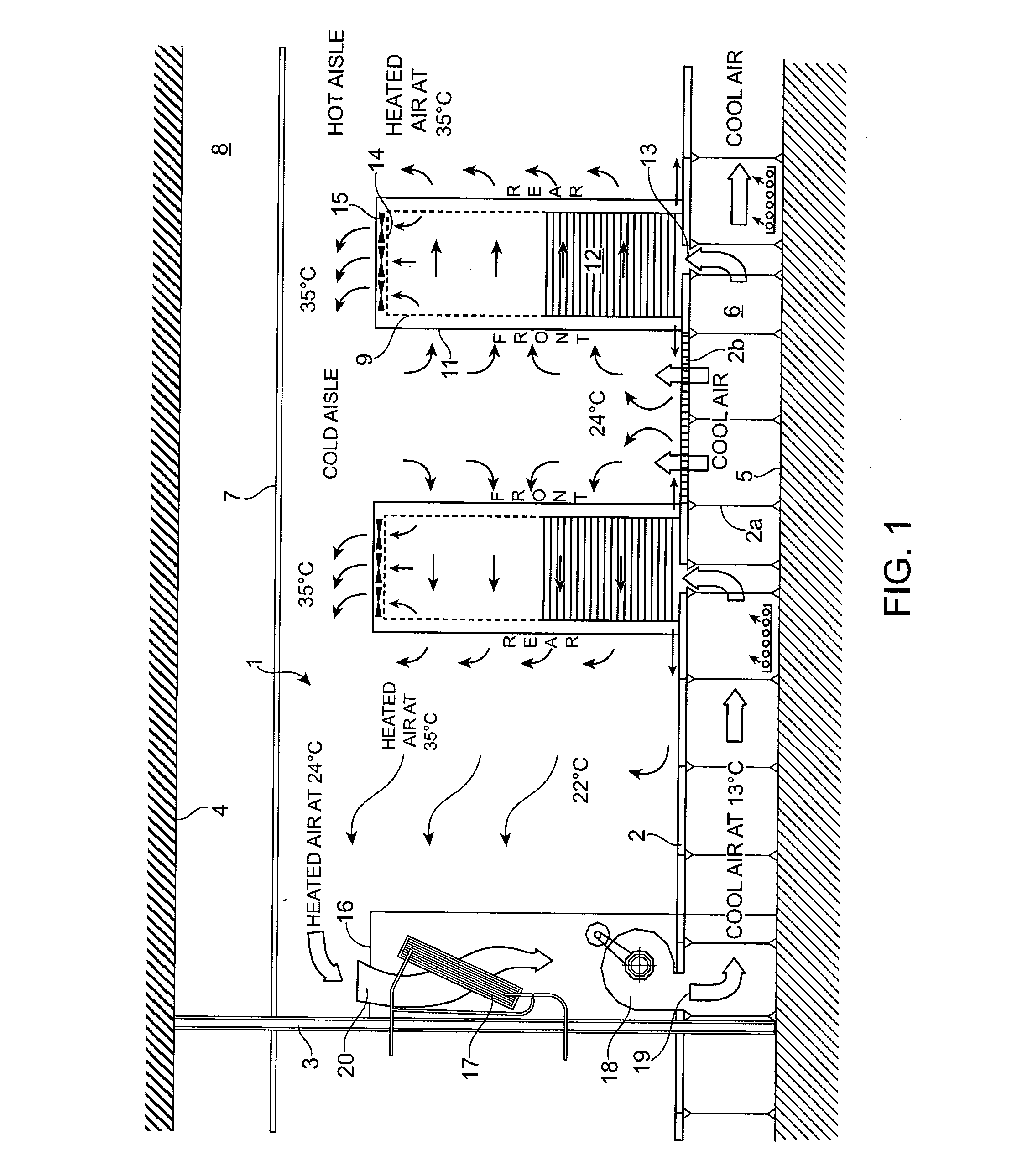
This cold ‘return’ or ‘bypass’ air disrupts the
heat transfer that could have been available to overloaded air conditioners, in such cases reducing the effectiveness of the CRAC units 16 to just 52% of their capacity.
While it is correct in principle to attempt to reduce the inlet
air temperature entering the rack cabinets 11 by increasing the
airflow rate through the perforated floor panels, this is an oversimplification.
This wastes supplied chilled air and, by mixing with the exhausted heated air from the rack cabinet 11, lowers the temperature of the exhausted air and therefore reduces the capacity of the installed air conditioners.
This results in insufficient static pressure close to the CRAC unit 16 to move the available cooling air up through the floor grilles 2b.
Worse still, in some cases, heated room air is actually sucked down into the floor void through the grilles 2b, reducing the
cooling capacity of the cooling airflow and creating ‘hot spots’.
However, in practice, such
physical separation is difficult to achieve in an open room environment particularly where
high heat loads are concerned.
Too often, however, these fans exhaust more air than the CRAC units 16 can deliver, thereby overwhelming their
cooling capacity.
Some studies have revealed that bypass air problems typically limit CRAC units to less than 35% of their ‘
nameplate’ rating.
In ‘hosted’ environments, close-coupled rack cabinets have earned the title ‘bad neighbor devices’, in that they take more than their share of the available cooling airflow.
However, as cooling loads or cabling and other sub-floor obstructions increase, their orientation becomes significant.
Placing more CRAC units 16 on the other two walls will almost certainly result in disrupted airflow / turbulence.
More CRAC units 16 can be added within the body of the technical space (which will typically be the case in wide data rooms) but this inhibits data rack
layout flexibility.
However, to provide stable
humidity, it is not advisable to equip each CRAC unit 16 with a humidifier.
This fails to provide a stable environment and pours significant energy down the condensate drain,
increasing risk, maintenance, repair and capital costs.
Conversely, lack of velocity can result in a cooled air supply stopping less than half way up the cabinet 11 and therefore not reaching equipment at higher levels.
This equipment will rely on cooling provided by the room air which is drawn through by the equipment fans, which room air may itself already be heated and of limited cooling capacity.
Forced convection directly through the bottom of the cabinet 11 may result in similar problems to those noted above.
In general, conventional rack cabinets are rather ‘leaky’ not just externally but also internally: for example, many have gaps between the rack itself and the cabinet
enclosure allowing cooled air to bypass the equipment within the cabinet and be wasted.
Even where this practice is followed, rising heat will tend to result in an accumulative heat build-up progressively towards the top of the rack cabinet.
However, upon examination, this is usually due to the load being created by relatively few devices.
Also, equipping the server itself affects the resistance to airflow.
Further, the loads of adjacent equipment directly impacts cooling capacity.
However, to be able to deliver this capacity, the size of the supply duct would need to be increased by raising the floor void height to 1500 mm of clear space (i.e. above any cabling also within the floor void, which is impractical for most data centers.
Even for new purpose-built facilities, this floor depth presents various technical challenges.
Predicting the effects of these various parameters with any certainty to achieve an optimized room configuration is extremely difficult.
Technology such as computational fluid dynamics (CFD)
software can assist greatly but this approach is not, as yet, widely adopted within the industry.
Many manufacturers do not make available the information necessary to undertake this task.
The result is that while some security disadvantages have been overcome by containment devices which contain
electrical equipment and are positioned in an environmentally controlled room, many of these existing installations risk overheating the equipment due to unexpectedly dense levels of deployment and poor or inadequate air extraction and ventilation.
Enclosed cabinets with perforated ceilings onto which fan kits can be attached to aid air circulation through the units are also known, but they are ineffectual in
high density applications.
Existing room-level solutions do nothing to address several issues with
raised floor technology, which include:
limited total cooling capacity with reasonable floor void heights;
wasted cooling air through poorly-managed cable
cut-outs and leaking floors and cabinets;
As racks are equipped out over time, adjustments are often not made to the
damper settings until there is a problem.
This may lead to a phenomenon called ‘static bypass’ which lowers the
cooling effect of the CRAC units, creating other hot spots.
However, the system is ‘open loop’ and so is still vulnerable due to complicated airflow patterns within a conventional system.
Similarly, the equipment in the rack is exposed to the other issues already discussed with conventional open rack cabinet systems, such as dust,
moisture, cold
smoke damage, security and
fire risk.
However, such a joint cannot be said to be leakproof, and combined with the use of
solenoid valve assemblies in the
pipe runs, as valves are a
potential source of leaks, the
pipe system may have leaks, even if dual-piped which is not a standard option.
The units are attached to the structural
soffit by
threaded rod and appropriate anchors, which means that this solution is not, at least primarily, a retrofit option but for new-build situations.
However, this level would not be achieved in reality as the system is effectively ‘open’ and subject to all the same room restrictions as for a pressurized
raised floor.
With edge-to-edge
abutment or substantially so, there is insufficient room to install light fittings or
overhead cable management (which is increasingly the preferred option among users), either of which would disrupt the airflow pattern if fitted below the cooling modules.
The raised floor can be used for static cabling and possibly dynamic cabling can be run overhead although even with spaced-apart modules, cabling along the line of the rack cabinet is not possible at a high level other than directly on top of the cabinets.
Actually the cabinet construction may not truly be sealed because in practice there may be visible gaps in the carcass construction, although there are sealing gaskets on the
doors.
However, this figure assumes that system losses do not reduce this saving even though it is still proposed to use the raised floor for cabling, and other factors such as leakage through the floor tiles.
Also, with this approach, in a retrofit situation, it may not be physically possible to install a suspended ceiling due to the amount of overhead service obstructions already existing.
Additionally, installing a suspended ceiling in a live data center may not be acceptable i.e. drilling into the structural
soffit to fix the suspension hangers and so on.
While loads of up to 8 kW of cooling are claimed for this solution, this may be difficult to achieve in practice, even assuming the greater fundamental efficiency due to the higher At.
However there are limitations on the depth or length of cabinet rows due to
air velocity factors—testing has indicated this to be at around 20 standard cabinets (600 mm wide).
Another issue with of this approach from a user's point of view relates to the lower airflow.
An OEM's products can be damaged by too high an airflow; especially, it is possible to ‘
windmill’ or cycle the small fans beyond their self-driven revolutions and shorten their life or indeed burn them out prematurely.
Overcooling can also prejudice the correct operation of a device.
On the other hand, too low an airflow can result in local overheating.
The cabinet
enclosure is, as already noted, leaky especially if the
enclosure is a single-
skin construction, especially if not insulated.
In general, other neighbouring hot devices are likely to
impact on the environment in a given cabinet.
While this system includes door seals, the overall cabinet construction does not appear to meet any recognized standard of ‘sealing’ classification.
How successful this system is in providing even airflow across all racked equipment is not known, but it would seem that the current levels of cabling required might be obstructed by these devices in high-density applications.
Multiple fans are provided for redundancy although it appears that it is necessary to 25 withdraw the complete fan tray to replace a failed fan, with the consequence that airflow is interrupted while this takes place.
The items containing
coolant are located low down in the
plinth reducing potential damage from leaks, although no means of leak containment seem to be provided.
Although described as a sealed system, this refers to ‘close fitting’ panels’ (single
skin non-insulated) and not a recognized seal standard or rating—thus the cabinet can only be used in data room environments and is subject to dust, cold
smoke, water etc. penetration.
However, although some of these products are sealed to a recognized standard, they do not have any means for
safeguarding the internal environment where the external environment is not benign, such as conditions of
high humidity,
partial pressure problems and so on.
A condensate drain is required with these products; excessive opening of
doors or poor seals can cause continuous drainage of condensate.
Units within the rack cannot be upgraded without shutting down the entire unit.
Neither of the Liebert or Stulz products is able to achieve the degree of cooling required by a fully-filled 42U-plus cabinet in a large data center.
Also, while their localized cooling provisions go some way toward reducing the
contamination and inefficiency issues of whole-room cooling, they still have inefficient and ill30 defined airflow within the cabinet.
For example, the top-down flow of
cold air from top-mounted
cooling units goes against the natural upward flow of warm air, and risks condensation problems as
moisture in the rising warm air meets the cold downward flow.
Moreover, there is still a risk that some servers will receive less cooling air than they should, and that failure of a server's internal fan will result in overheating.
This inevitably results in waste of money and resources if the data center does not quickly reach its expected capacity.
Conversely, if the data center quickly exceeds its expected ‘capacity, there is a lengthy lead-time because additional power allocation after initial request from a data center tends to be extremely slow.
The result is that tenants usually request more power than they need initially, leading to a
scalability problem because power infrastructure needs to be installed for the entire data center from the outset day even if there are only a few tenants at that stage.
If too much site infrastructure capacity is installed, then those making the investment recommendations will be criticized for the resulting low site-equipment utilization and poor efficiency.
However if too little capacity is installed, a company's IT strategy may be constrained, or new services may have to be outsourced because there is no space with sufficient site infrastructure capacity to do the work internally.
Summarizing all of the above, those skilled in the art know that thermal characteristics and airflow movement within a typical data room environment are extremely complicated and, to a large extent, full of uncertainty.
As cooling loads increase, this becomes more critical.
Above this level, it becomes necessary to either spread equipment out widely, which may not be practical or cost effective, or to place restrictive limits on the number of hot devices that can be deployed within a rack.
Currently, such limits are often forced on users due to the action of thermal triggers within the electronic equipment.

