Device and Method For Preparing a Homogeneous Mixture Consisting of Fuel and Oxidants

a technology of oxidants and devices, which is applied in the direction of gaseous fuels, burner details, capillary burners, etc., can solve the problems of reducing the useful life, difficult stable operation, and evaporating fuel through non-woven metal fiber mats, so as to reduce the thermal stress of surrounding components, reduce the sooting tendency of the system, and reduce the effect of thermal stress

Inactive Publication Date: 2008-06-12
EHNERDEJ GMBKH
View PDF8 Cites 16 Cited by
  • Summary
  • Abstract
  • Description
  • Claims
  • Application Information

AI Technical Summary

Benefits of technology

[0029]The invention is based on having discovered that, by providing a packed structure, particularly in conjunction with the further features of the device, the drawbacks of prior art can now be at least partially overcome. Thus, because the air ratio is set defined in the mixing chamber, the evaporator can now be operated so that low temperatures materialize there, so that spontaneous self-ignition is avoided. These low temperatures diminish the sooting tendency of the system, e.g., as prompted by cracking reactions. The mixture forming zone and oxidation zone are now practically separated, thus, doing away with the need for a mol seal. The temperatures in the evaporator are very low and near independent of output, thus correspondingly reducing the thermal stress of the surrounding components. The hydrocarbons can now be selectively partially oxidized in a first reaction stage by means of a catalyst thus minimizing non-selective ways of reaction, particularly cracking and soot forming.
[0030]Making use of a non-catalytic first reaction stage has the advantage that the first reaction stage can now be operated at higher temperatures since catalysts can deactivate at excessively high temperatures. Because of the air ratio being defined, engineered control of the formation

Problems solved by technology

Evaporating fuel by means of non-woven metal fiber mats has drawbacks, however.
The drawback here is that the fuel comes into contact with the air only at the surface of the non-woven mat and can thus oxidize.
The corresponding low air ratio at the surface of the non-woven mat results in deposits forming on the evaporator which make stable operation difficult and diminishes the useful life.
Reaction conditions exist comparable to those in steam cracking, resulting in the system becoming clogged with soot as briefly explained below.
The cited compounds are, however, highly reactive under the operating conditions that predominant in steam cracking and tend toward condensation and polymerization reactions, resulting in the end in soot being formed and clogging up the reaction coils to the detriment of the corresponding heat throughput, and thus, requiring cracking coils to be regularly replaced.
Soot formation in an evaporator or combustion chamber can negatively influence the evaporator and combus

Method used


Image

  • Device and Method For Preparing a Homogeneous Mixture Consisting of Fuel and Oxidants
  • Device and Method For Preparing a Homogeneous Mixture Consisting of Fuel and Oxidants
  • Device and Method For Preparing a Homogeneous Mixture Consisting of Fuel and Oxidants

Examples


first embodiment

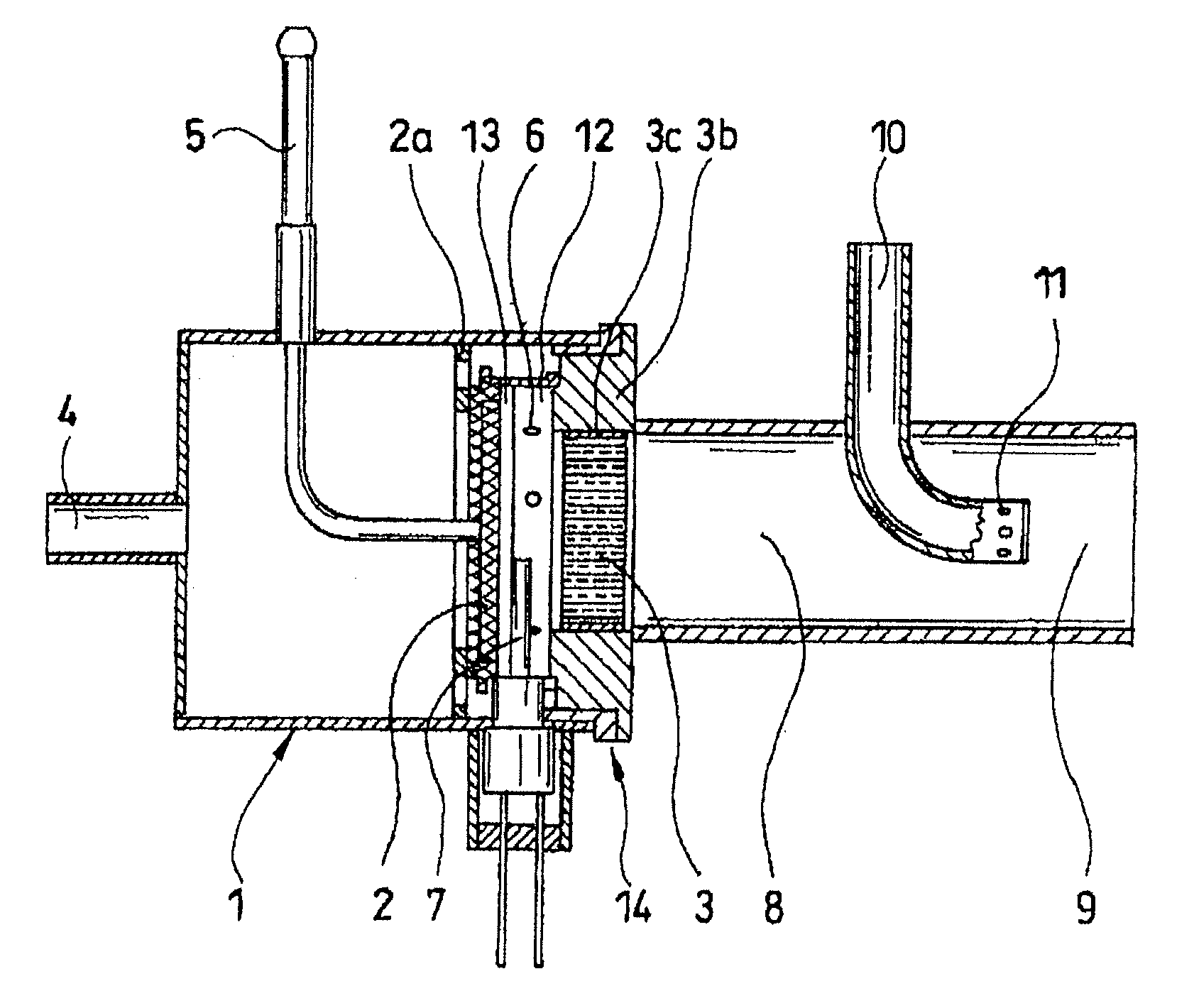
[0037]Referring now to FIG. 1, there is illustrated a system for providing a homogenous fuel / air mixture on the basis of liquid fuel. The core component of the system for providing a homogenous fuel / air mixture on the basis of liquid fuel as shown in FIG. 1, as an example, is the fuel evaporator 2 arranged in an evaporator element 1, attached to which is a supporting element 3b for mounting a packed structure 3 which may be jacketed by a fiber mat 3c for mechanical fixation and thermal insulation respectively.

[0038]Liquid fuel and oxidant are supplied to the system via the fuel feeder 5 and oxidant feeder 4 respectively. The oxidant, preferably air, with optional additives, such as, e.g., steam, enters via radially inwardly directed ports 6 into the mixing chamber 12 where the oxidant is mixed with the fuel that has been evaporated in an evaporation chamber 13 that is located upstream of the mixing chamber 12. In general, the evaporation chamber 13 and the mixing chamber 12 form a s...

second embodiment

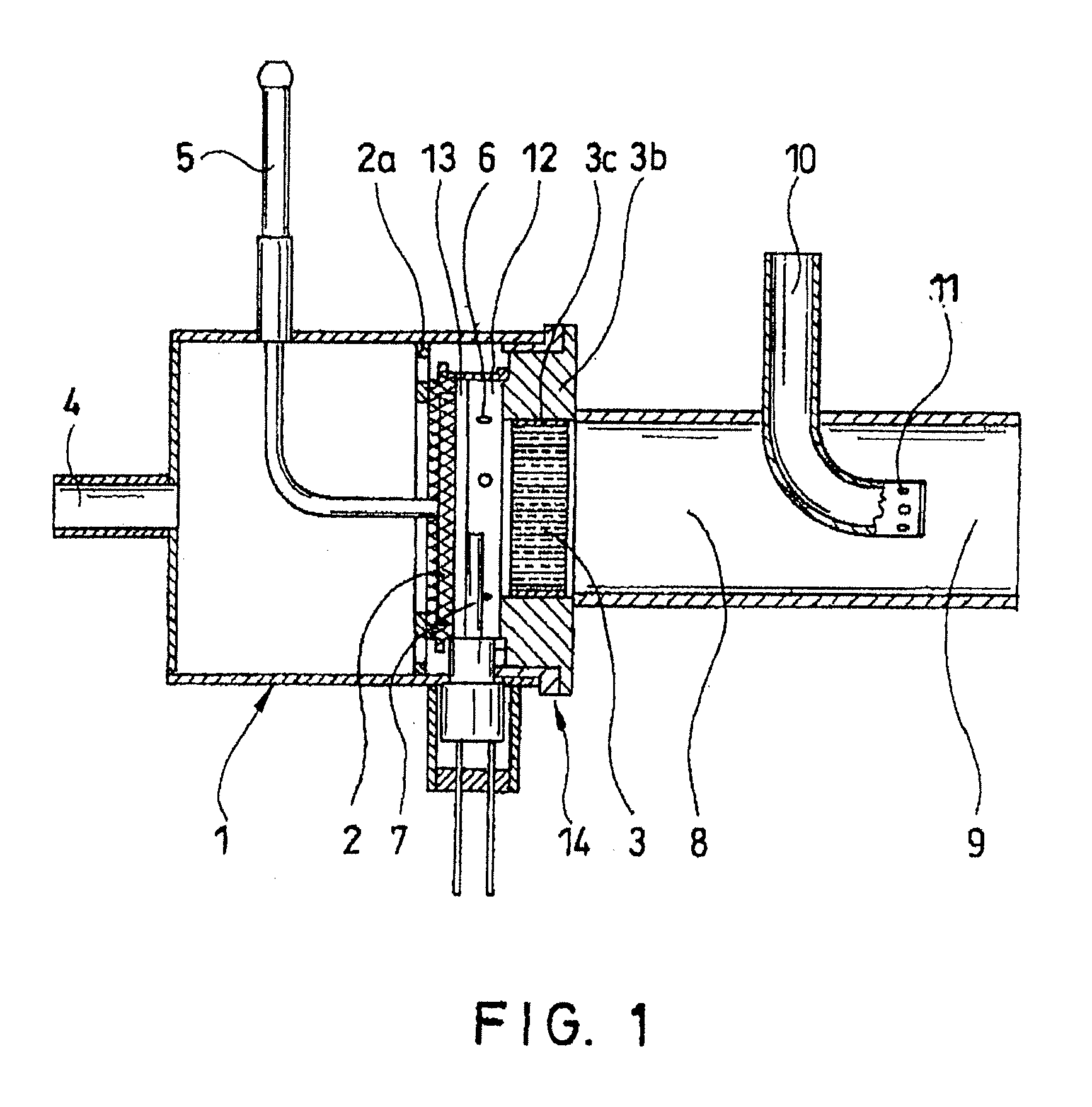
[0041]Referring now to to FIG. 2, there is illustrated a diagrammatic representation of a system for providing a homogenous fuel / air mixture on the basis of liquid fuel. Unlike the embodiment of FIG. 1, the supply of the oxidant flow in the second reaction zone is multiply stepped and oriented radially inwards via a plurality of ports 11.

[0042]Referring now to FIG. 3, there is illustrated a graph plotting temperature and output curves as a function of time as is relevant to a device in accordance with the invention. Shown are the exemplary results obtained with such a system with diesel evaporation in air. The packed structure 3 employed contains a catalyst which partially oxidizes the diesel fuel so that a hydrogen-rich gas mixture materializes. This can be made use of in, e.g., an auxiliary power unit (APU) for generating electricity and heat. FIG. 3 plots the temperatures as measured in the evaporator chamber (curve a) and in the catalyst (curve b) for the thermal outputs (curve ...


PUM

PropertyMeasurementUnit
Diameteraaaaaaaaaa
Diameteraaaaaaaaaa
Temperatureaaaaaaaaaa

Abstract

A device for providing a homogenous mixture of fuel and oxidant including an arrangement (5) for feeding liquid fuel to an evaporator, an arrangement (4) for feeding gaseous oxidant into a mixing zone (12) downstream of the evaporator, and a reaction zone downstream of the mixing zone in which a packed structure (3) is arranged. The packed structure can be a ceramic cylindrical molding having a diameter in the range 25 to 35 mm and an axial length in the range 15 to 50 mm or it can have flow conduits that are square in cross-section and have a cell density in the range 400 to 1200 cpsi.

Description

BACKGROUND OF THE INVENTION[0001]1. Field of the Invention[0002]The invention relates to a device for providing a homogenous mixture of fuel and oxidant including means for feeding liquid fuel to an evaporator, means for feeding gaseous oxidant into a mixing zone downstream of the evaporator, and a reaction zone downstream of the mixing zone. The invention also relates to a method for providing a homogenous mixture of fuel and oxidant including the steps of: feeding liquid fuel to an evaporator, feeding gaseous oxidant and evaporated fuel into a mixing zone downstream of the evaporator, mixing oxidant and fuel in the mixing zone and introducing the mixture having materialized in the mixing zone into a reaction zone.[0003]2. Description of Related Art[0004]Presently, liquid fuels, such as diesel, fuel oil, gasoline, and kerosene represent the most important source of energy for generating heat, mechanical work and electric current, this also being used, e.g., in automotive engine com...

Claims


Application Information

Patent Timeline
IPC IPC(8): C10L3/10B01F3/02B01J19/24B01F23/10
CPCB01B1/005F23D2212/20B01J19/2485B01J19/26B01J2208/00849C01B3/386C01B2203/0261C01B2203/1023C01B2203/1247C01B2203/1276C01B2203/1288F23D3/40F23D2203/102F23D2203/105F23D2203/107F23D2212/10B01J4/002B01J19/24B01B1/00
Inventor KAH, STEFANLINDERMEIR, ANDREASENGEL, ROBERT
Owner EHNERDEJ GMBKH
Why Eureka
Try Eureka