Coronary stent having a surface of multi-layer immobilized structures

a multi-layer immobilized structure and coronary artery technology, applied in the field of coronary artery stents having a surface of multi-layer immobilized structures, can solve the problems of limited hemocompatibility of conventional stainless steel coronary artery stents, severe thrombosis of conventional coronary artery stents, and inability to improve the effectiveness of hemocompatibility of using only polysaccharide for coating the stainless steel coronary artery s

Inactive Publication Date: 2008-08-28
NAT TAIWAN UNIV OF SCI & TECH
View PDF12 Cites 7 Cited by
  • Summary
  • Abstract
  • Description
  • Claims
  • Application Information

AI Technical Summary

Benefits of technology

[0009]A primary objective of the present invention is to provide a stent for coronary vessels having a surface of multilayer immobilized structures, which is able to overcome the issues and problems of conventional technology, and to improve the hemocompatibility of the conventional coronary stent, and also further providing functionality as a drug-eluting coronary stent.

Problems solved by technology

On the other hand, the problem of stent thrombosis when using conventional coronary stent is very severe, even to the extent of having 2-5% of patients suffering from subacute stent thrombosis.
However, the conventional stainless-steel stent does not possess adequate hemocompatibility; therefore, many researchers have attempted to improve the hemocompability of stainless-steel stent.
However the ability to improve the effectiveness for hemocompatibility of using only polysaccharide for coating the stainless-steel coronary stent is still rather limited, as this type of coronary stent cannot completely resolve the thrombus issue.
However, the conventional heparin cannot be securely disposed on the surface of the polymer.
However, this type of slight modification produces yet still unsatisfactory results; the heparin that is secured on the stent still would be released quickly, thus making the stent to lose its anticoagulant effectiveness after implanting into living tissues.

Method used


Image

  • Coronary stent having a surface of multi-layer immobilized structures
  • Coronary stent having a surface of multi-layer immobilized structures
  • Coronary stent having a surface of multi-layer immobilized structures

Examples


first embodiment

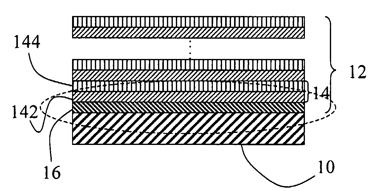
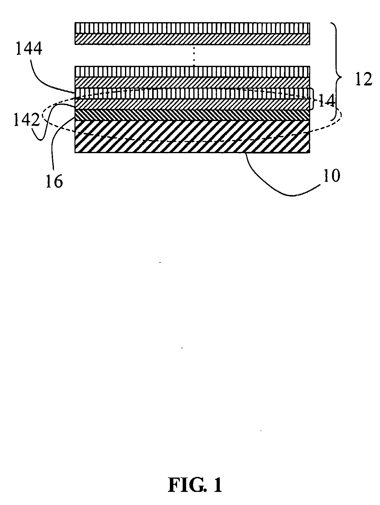
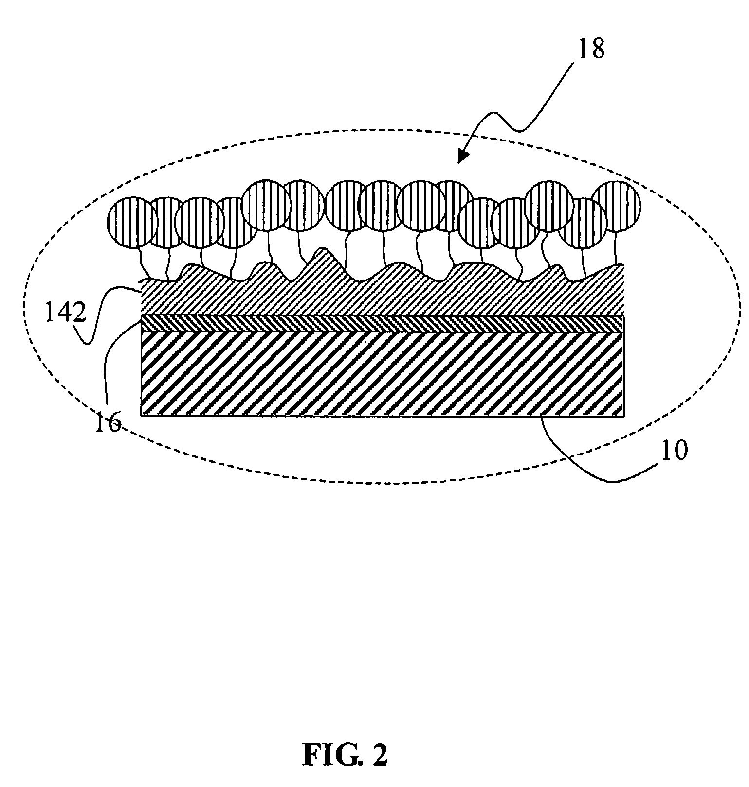
Apparatus for Coronary Stent

[0031]First, surface modification is performed on a stainless-steel plate (SUS316L). The stainless steel plate, prior to being heated at 500° C., is firstly ultrasonic-vibrated three times inside an acetone solution, and later is soaked in nitric acid for 20 minutes, thereby removing the impurities from the stainless-steel surface. The stainless steel plate after the aforementioned cleaning process is hereby referred to as “pure SS”.

[0032]The stainless-steel plate using aminotrimethoxysilane (ATMS) is taken to perform silylation, wherein the stainless-steel plate is soaked inside 1 wt % ATMS toluene solution, and also agitation under ultrasound for one hour is performed. After cleaning using toluene and ethanol, finally again sonic vibration is performed for 5 minutes. Then it is air dried. The sample produced is thereby referred to as “SS-ATMS”.

[0033]The “SS-ATMS” stainless steel plate is then soaked at 25° C. in 20 ml distilled water containing 0.5 g of...

second embodiment

[0037]The stent sample which has underwent surface modification as fabricated in the first embodiment has its surface hydrophilicity measured using a goniometer and assessed using the water contact angle (θ). The stainless steel sample, after surface modification, is using Mg as the anode, and is analyzed under XPS at 1253.6 eV and 150 W of power. Scanning measurements are performed using a variety of eVs to O1s, Si2p, N1s, and S2p. The surface roughness is inspected using atomic force microscopy (AFM).

[0038]FIG. 3 illustrates the contact angles between the surface-modified stainless steel samples and distilled water. After performing heat treatment (74.0°) and nitrate immersion (59.5°) at 500° C., the contact angles are lower than the untreated stainless steel sample (85.2°), and later the silylation clearly changes the surface wettability. Wherein is visible after silylation is to be embedded in the HA and HEP steps (namely, SS-ATMS-HA and SS-ATMS-HA-HEP) when compared with SS-ATM...

third embodiment

[0042]30 ml of human blood is retrieved from a healthy donor and is mixed with a liquid solution containing 0.136 M D-glucose, 75 mM sodium citrate, and 0.4 mM citric acid. Later, the human blood is centrifuged under 300 g at 4° C. for 20 minutes for separating the blood corpuscles from the platelet-rich plasma (PRP). Later, a portion of the PRP is removed and centrifuge is performed under 2000 g at 4° C. for 20 minutes to obtain the platelet-poor plasma (PPP) to provide for the human plasma-protein adsorption test. The substrate material is placed in 0.5 ml of PPP at under 37° C. for 1 hour. The activated partial thrombin time (APTT) for the PPP undergoing reaction, the prothrombin time (PT), the fibrinogen time (FT), and the thrombin time (TT) are measured using an automated blood coagulation analyzer during testing. In addition, testing is performed to test tubes containing no test samples as the control group.

[0043]The blood coagulation cascade includes intrinsic pathway, extrin...


PUM

PropertyMeasurementUnit
contact anglesaaaaaaaaaa
binding energyaaaaaaaaaa

Abstract

A stent for coronary vessels, having a surface of multilayer immobilized structures, includes a stent body and a number of polyelectrolyte complex (PEC) layers stacking and being immobilized on the surface of the stent body, in which the PEC layer is formed of a polymer layer and an anticoagulant layer. The coronary stent is capable of effectively improving the hemocompatibility longevity over conventional stent using surface encapsulation of an anticoagulant layer for hemocompatibility improvement. Furthermore, the coronary stent can be use as a drug-eluting coronary stent, thus allowing for the time-releasing of drugs, and further preventing the thickening of vascular smooth muscle cells for causing vascular thrombosis.

Description

BACKGROUND OF THE INVENTION[0001]1. Field of the Invention[0002]The present invention relates in general to a stent for blood vessels, and in particular to a stent for coronary vessels having a surface of multilayer immobilized structures.[0003]2. The Prior Arts[0004]Coronary stent currently has been widely adopted in connection with percutaneous transluminal coronary angioplasty (PTCA) for use in the treatment of coronary arterial diseases. The coronary stent is mainly used in emergency percutaneous coronary intervention; therefore, the most important function of the implanted coronary stent is to prevent restenosis. On the other hand, the problem of stent thrombosis when using conventional coronary stent is very severe, even to the extent of having 2-5% of patients suffering from subacute stent thrombosis.[0005]Conventional stent typically is made from stainless-steel (SS), and is used for opening blocked blood vessels. However, the conventional stainless-steel stent does not poss...

Claims


Application Information

Patent Timeline
Patent Type & Authority Applications(United States)
IPC IPC(8): A61F2/06
CPCA61L31/10A61L31/16A61L2300/41A61L2300/62A61L2300/42A61L2300/432A61L2300/416
Inventor YANG, MING-CHIENHWANG, JUEY-JENHUANG, LI-YINGLIU, TING-YU
Owner NAT TAIWAN UNIV OF SCI & TECH
Why Eureka
Try Eureka