Sorbent fiber compositions and methods of temperature swing adsorption

a technology of sorbent fibers and compositions, applied in the direction of machine operation, lighting and heating apparatus, separation processes, etc., can solve the problems of aging of the pc power station infrastructure, adverse effects on agriculture and biodiversity, and rising sea levels

Active Publication Date: 2009-01-29
GEORGIA TECH RES CORP +1
View PDF13 Cites 87 Cited by
  • Summary
  • Abstract
  • Description
  • Claims
  • Application Information

AI Technical Summary

Benefits of technology

[0013]Various embodiments of the present invention are directed to the composition and use of adsorbent fiber compositions. More particularly, various embodiments of the present disclosure are directed towards adsorbent materials and their use in temperature swing adsorption processes. Broadly

Problems solved by technology

Increased concentrations of CO2 in the earth's atmosphere aggravate the greenhouse gas effect and lead to unwanted climate change, with consequent risks of extreme weather, rising sea levels, and adverse effects on agriculture and biodiversity.
The PC power station infrastructure is aging, and current carbon capture methods are prohibitively expensive to be implemented as-is.
One of the main hurdles for CCS is the cost of capture.
The process of post-combustion CO2 capture with low pressure feeds, low temperature feeds, and massive flow rates is one of many difficult aspects of the CCS challenge.
Pressure drop through the adsorbent column should be minimized, because high fluid pressure drop can cause movement or fluidization of the adsorbent particles, resulting in serious attrition and loss of the adsorbent.
A slow adsorption rate, due to large mass transfer resistance, will result in a long mass transfer zone (MTZ) within which the adsorbent is only partially saturated with adsorbate.
A long mass transfer zone, which contains a large quantity of partially utilized adsorbent, will, therefore, result in a short adsorption step and inefficient use of the

Method used


Image

  • Sorbent fiber compositions and methods of temperature swing adsorption
  • Sorbent fiber compositions and methods of temperature swing adsorption
  • Sorbent fiber compositions and methods of temperature swing adsorption

Examples


example 1

Fiber Composition Design

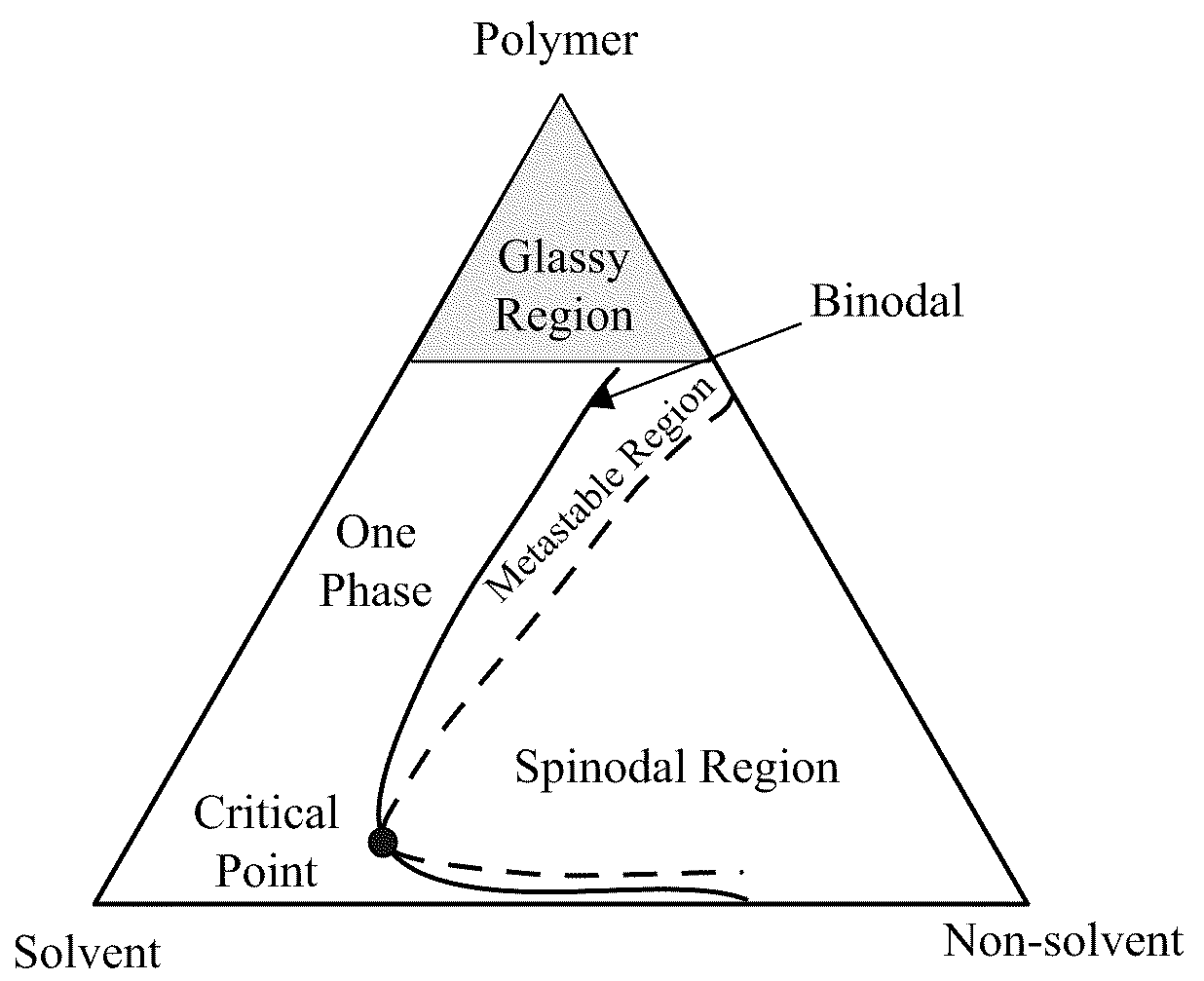
[0089]In the present example, a novel hollow fiber based solid sorbent system is considered. The hollow fiber formation is based on the well-known non-solvent phase inversion technique commonly referred to as “wet-spinning” in the field. Polymer solutions comprising solvents, non-solvents, and additives such as lithium nitrate are extruded through a die into a non-solvent quench bath. The non-solvent bath provides the driving force for mass-transfer between the quench bath and the solvent present in the nascent fiber, which results in micro-phase separation and the formation of a porous fiber. The phase separation is best visualized using a ternary phase diagram for the polymer / solvent / non-solvent solution, as seen in FIG. 3. The binodal line represents the divide between one-phase and two-phase regions, and the two-phase region can be further divided into the metastable region and the unstable spinodal region. Spin solutions are made such that the solution e...

example 2

Fiber System Design

[0091]A post-combustion carbon capture system was designed based on a mixed matrix hollow fiber platform. The mixed matrix hollow fiber platform was chosen for several reasons. First, higher sorption efficiencies can be achieved by utilizing the hollow fiber morphology for supplying cooling agents in the bore of the fiber during sorption and heating agents in the bore during desorption. Secondly, the thin porous walls of the fiber allow for very rapid heat and mass transfer times, a necessity in such demanding feeds. Finally, in the design, the heating and cooling agents in the fibers can simply be steam and water, therefore removing any waste by-products associated with the system.

[0092]The fiber system was designed using a two bed system with no guard bed for a pseudo-steady state continuous operation. The bed actively sorbing CO2 will have liquid water passing through the bores of the fibers, and the bed actively desorbing will have steam passing through the bo...

example 3

Experimental Methodology

[0113]N-methyl-pyrrolodine (NMP) (ReagentPlus™ 99%, Sigma-Aldrich, Milwaukee, Wis.) was used as the solvent in the polymer solutions because it is miscible in water and a strong solvent for cellulose acetate. Methanol (99.8%, ACS Reagent, Sigma-Aldrich) and hexanes (ACS Reagent, >98.5%, Baker) were used for the solvent exchange portion of the fiber formation. Methanol was used to remove excess water from the fibers, and hexanes were used to exchange excess methanol from the fibers. The intent is to replace high surface tension fluids with lower surface tension fluids to prevent capillary forces from collapsing the pore structure during drying. All solvents and non-solvents were used as-received with no purification or modification.

[0114]Zeolite 13X (1-3 micron particles, Sigma-Aldrich) was chosen as the sorbent to be dispersed into the polymer matrix. Once received, the zeolites were dried at 230° C. to drive off any excess organics from synthesis. After dryi...


PUM

PropertyMeasurementUnit
Lengthaaaaaaaaaa
Lengthaaaaaaaaaa
Percent by massaaaaaaaaaa

Abstract

The various embodiments of the present invention relate to compositions, apparatus, and methods comprising sorbent fibers. More particularly, various embodiments of the present invention are directed towards sorbent fiber compositions for temperature swing adsorption processes. Various embodiments of the present invention comprise sorbent fiber compositions, apparatus comprising a plurality of sorbent fibers, and methods of using the same for the capture of at least one component from a medium, for example CO2 from flue gas.

Description

RELATED APPLICATIONS[0001]This application claims, under 35 U.S.C. § 119(e), the benefit of U.S. Provisional Patent Application Ser. No. 61 / 051,595, filed 8 May 2008, and U.S. Provisional Patent Application Ser. No. 60 / 946,475, filed 27 Jun. 2007, the entire contents and substance of which are hereby incorporated by reference as if fully set forth below.TECHNICAL FIELD[0002]The various embodiments of the present disclosure relate generally to sorbent fiber compositions. More particularly, various embodiments of the present disclosure are directed towards sorbent fibers for temperature swing adsorption processes.BACKGROUND OF THE INVENTION[0003]Coal plants provide the majority of the United States' power and are major point sources for greenhouse gas emissions, such as carbon dioxide (CO2). Developing countries are rapidly building coal power stations at a rate which will add greatly to atmospheric CO2 levels. The most common form of coal power stations are Pulverized Coal (PC) type ...

Claims


Application Information

Patent Timeline
IPC IPC(8): B01D53/02C01B32/50
CPCB01D53/0438B01D2253/108B01D2253/34B01D2257/504Y10T428/2935B01J20/28023Y02C10/08Y10T428/2922B01D2259/4009B01J20/18B01J20/226B01J20/261B01J20/262B01J20/3483B01J20/3425B01J20/3293Y02C20/40
Inventor LIVELY, RYANCHANCE, RONALD R.KOROS, WILLIAM J.DECKMAN, HARRYKELLEY, BRUCE T.
Owner GEORGIA TECH RES CORP
Why Eureka
Try Eureka