Alloy with high glass forming ability and alloy-plated metal material using same

Inactive Publication Date: 2009-10-01
NIPPON STEEL CORP
View PDF6 Cites 9 Cited by
  • Summary
  • Abstract
  • Description
  • Claims
  • Application Information

AI Technical Summary

Benefits of technology

[0062]For example, it becomes possible to produce a bulk metallic glass by high pressure die-casting using a metal casting mold having a high productivity and enabling production of a bulk shape alloy.
[0063]

Problems solved by technology

Currently, the alloys utilizing the high glass forming ability of the metalloid elements of B, Si, or P to obtain bulk metallic glasses are limited to alloys based on the iron-group elements of Fe, Co, and Ni.
However, the Cu-based bulk metallic glasses up to now, as described in Japanese Patent Publication (A) No. 2002-256401, are systems of components using Zr, Hf, or other expensive elements.
If judged from the combinations of elements of amorphous alloys discovered up to now, the elements particularly difficult to obtain bulk metallic glasses from as base-elements are metal elements which, while belonging to the group of elements with small atomic radii, have relatively large atomic radii among the group of elements with small atomic radii.
However, these alloys cannot be said to be high in glass forming ability.
Bulk metallic glasses still cannot be obtained.
If the melting point of the base element is low, in a composition with a high concentration of the low melting point element, it is difficult to form a deep eutectic point.
This is also a reason why it is difficult to improve the glass forming ability in Al-based alloys and Zn-based alloys.
Even if using a copper casting mold for high pressure die-casting, an amorphous phase can only be obtained at the surface layer part.
In t

Method used


Image

  • Alloy with high glass forming ability and alloy-plated metal material using same
  • Alloy with high glass forming ability and alloy-plated metal material using same
  • Alloy with high glass forming ability and alloy-plated metal material using same

Examples


example 1

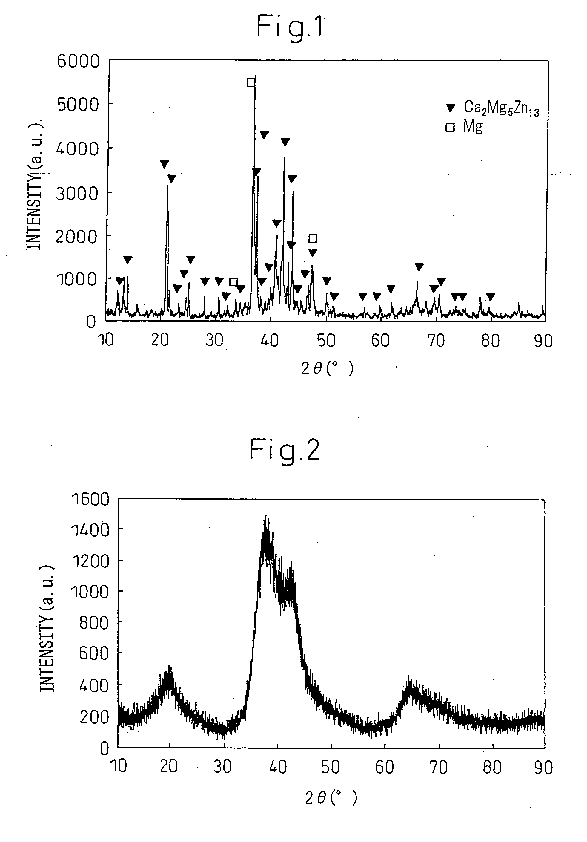
[0219]Zn, Mg, and Ca metal reagents (purity 99.9 mass % or more) were mixed and melted using a high frequency induction heating furnace in an Ar atmosphere at 600° C., then furnace cooled to obtain a Zn: 50 atm %, Mg: 45 atm %, Ca: 5 atm % chemical composition furnace cooled alloy.

[0220]This furnace cooled alloy had an X-ray diffraction chart as shown in FIG. 1. With this composition, as an equilibrium phase, the intermetallic compound Ca2Mg5Zn13 is formed.

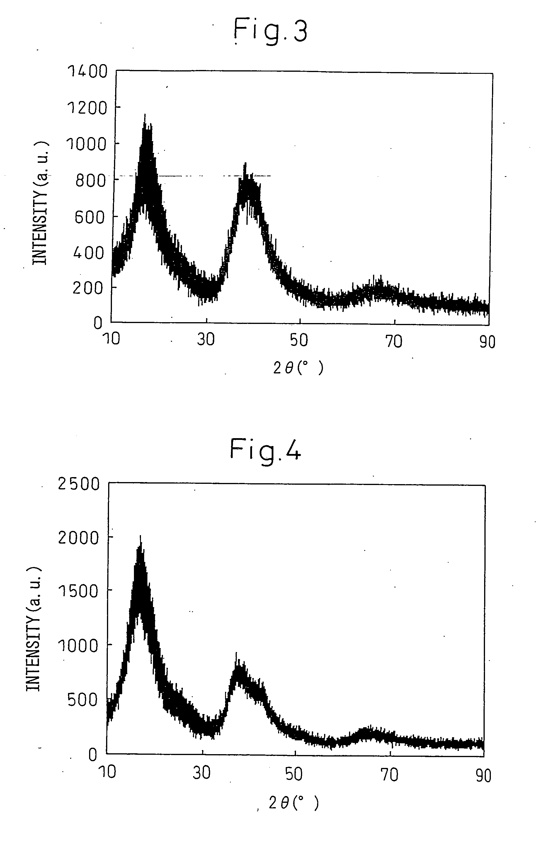
[0221]The alloy of said composition was used to fabricate a thin strip sample by the single roll method. The thin strip sample was fabricated using a Nisshin Giken single roll apparatus (RQ-1).

[0222]A quartz crucible having a slit-shaped aperture (0.6 mm×20 mm) at its bottom end was charged with the alloy to 0.1 kg and heated. The alloy was held at a temperature 100° C. higher than the melting point of 346° C. (619K) for 5 minutes, then the molten alloy was ejected on to a Cu roll (roll diameter 300 mm) rotated at a peripheral spe...

example 2

[0225]Zn, Al, Mg, and Ca metal reagents (purity 99.9 mass % or more) were mixed and melted using a high frequency induction furnace in an Ar atmosphere at 600° C., then furnace cooled to obtain the a furnace cooled alloy of a chemical composition of Zn:45 atm %, Mg:50 atm %, and Ca:5 atm %.

[0226]This alloy was used to fabricate a thin strip sample by the single roll method. For fabrication of the thin strip sample, a single roll apparatus (RQ-1) made by Nisshin Giken was used.

[0227]A quartz crucible having a slit-shaped aperture (0.6 mm×20 mm) at its front end was charged with 0.1 kg of the alloy and heated. The alloy was held at a temperature of 100° C. higher than the melting point 373° C. (646K) for 5 minutes. The molten alloy was ejected at a pressure of 0.03 MPa on a Cu roll (roll diameter 300 mm) rotated at a peripheral speed of 50 m / sec.

[0228]The distance between the aperture and roll surface at the time of ejection was 0.2 mm. The obtained thin strip sample had a width of 3 ...

example 3

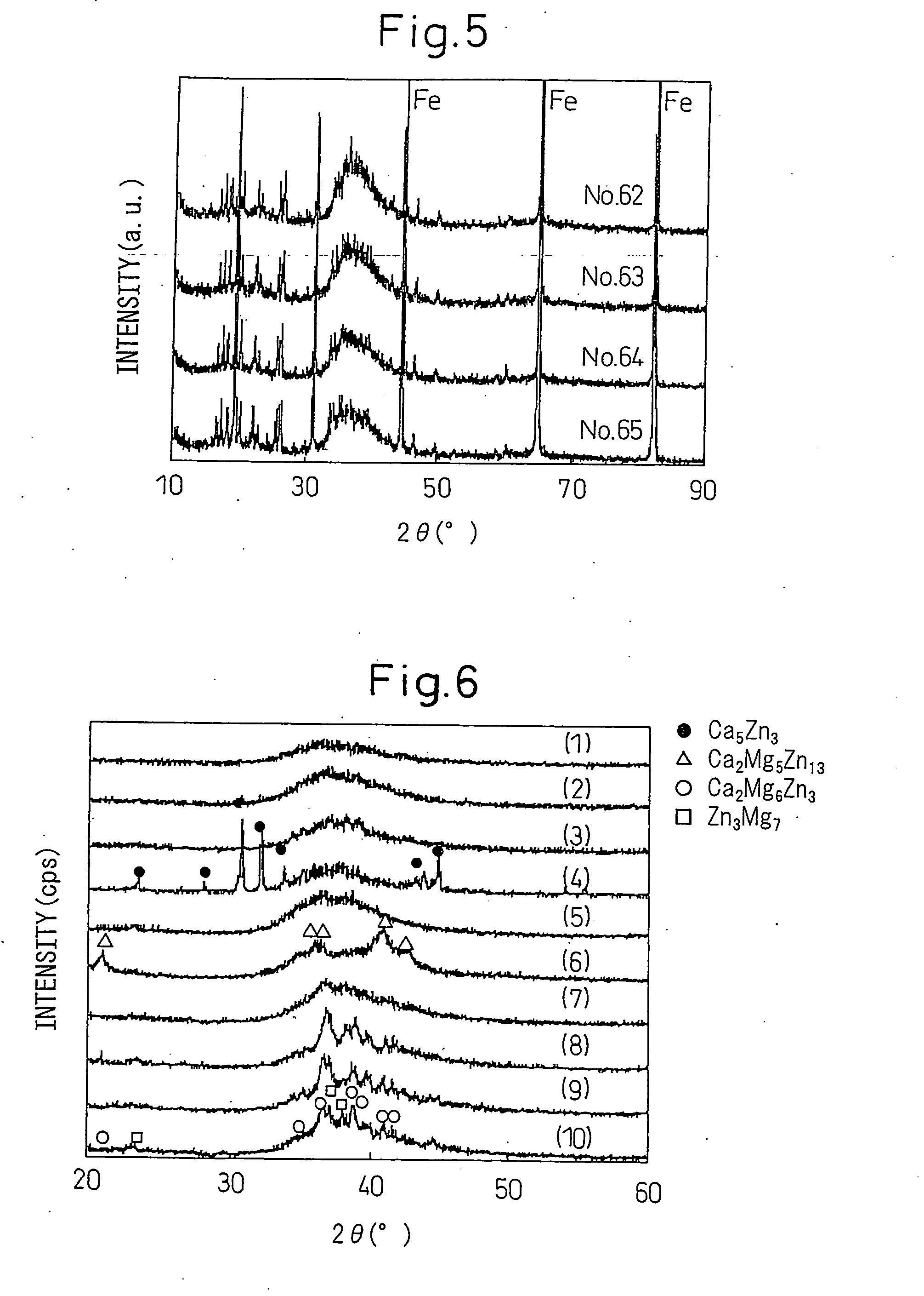
[0230]Different metals (purity 99.9 mass % or more) were mixed in predetermined amounts and melted using a high frequency induction heating furnace in an Ar atmosphere at 600 to 1100° C., then were furnace cooled to obtain alloys of the chemical compositions of Nos. 1 to 48 shown in Table 1 and Table 2 (continuation of Table 1).

[0231]The chemical compositions of the different alloys were determined by ICP (inductively-coupled plasma) spectrometry using acid-solution dissolving swarf obtained from the alloys.

[0232]To fabricate amorphous samples of the alloys of the above chemical compositions, the single roll method was used.

[0233]Using an apparatus the same as the one used in Example 1, quartz crucibles having slit-shaped apertures (0.6 mm×20 mm) at their front ends were charged with 0.1 kg amounts of these alloys. The alloys were held at temperatures 80 to 200° C. higher than the melting points (Tm) for several minutes. The molten alloys were ejected at pressures of 0.02 to 0.03 MP...


PUM

PropertyMeasurementUnit
Fractionaaaaaaaaaa
Fractionaaaaaaaaaa
Nanoscale particle sizeaaaaaaaaaa

Abstract

An alloy with a high glass forming ability characterized by containing a group of elements A with atomic radii of less than 0.145 nm of a total of 20 to 85 atm %, a group of elements B with atomic radii of 0.145 nm to less than 0.17 nm of a total of 10 to 79.7 atm %, and a group of elements C with atomic radii of 0.17 nm or more of a total of 0.3 to 15 atm %; when the elements with the greatest contents in the group of elements A, group of elements B, and group of elements C are respectively designated as the “element a”, “element b”, and “element c”, by the ratio of the content of the element a in the group of elements A (for example, Zn and/or Al), the ratio of the content of the element b in the group of elements B (for example, Mg), and the ratio of the content of the element c in the group of elements C (for example, Ca) all being 70 atm % or more; and by the liquid forming enthalpy between any two elements selected from the element a, element b, and element c being negative.

Description

TECHNICAL FIELD[0001]The present invention-relates to an amorphous alloy and alloy-plated metal material, more particularly relates to an alloy with a high glass forming ability and an alloy-plated metal material with a high corrosion resistance or high heat reflectance using the same.BACKGROUND ART[0002]Research relating to amorphous alloys in recent years have concentrated on searches for obtaining amorphous structures even with small cooling rates, that is, so-called bulk metallic glasses. Up until now, alloy compositions giving bulk metallic glasses have been discovered by numerous systems of components.[0003]In Japan, Tohoku University's Inoue et al. have been engaged in cutting edge research. The fact that since 1988, Mg—La—(Ni,Cu)-based alloys, lanthanide-Al-transition metal-based alloys, Zr—Al-transition metal-based alloys, and Pd—Cu—Ni—P-based alloys giving bulk metallic glasses have been discovered is explained in Akihisa Inoue, Akira Takeuchi, Material Science and Enginee...

Claims


Application Information

Patent Timeline
IPC IPC(8): C22C23/02C22C18/00C22C21/06C22C23/04
CPCY10T428/12493C22C21/06C22C45/001C23C30/00C22C45/00C22C1/002C23C4/121C22C21/12C23C2/04C23C2/12C23C2/06Y10T428/12799C22C45/08C22C45/005C22C18/00C23C4/123C22C1/11C23C2/26
Inventor TOKUDA, KOHEINOSE, KOICHISATO, YUICHINAKAZAWA, MAKOTO
Owner NIPPON STEEL CORP
Why Eureka
Try Eureka