
Hollow microparticles

a technology of hollow microparticles and microparticles, which is applied in the direction of microcapsules, capsule delivery, drug compositions, etc., can solve the problems of limited surface thickness (typically nanoscale), limited range of options compared to inorganic particles, and insufficient stability of limited surface thicknesses

Inactive Publication Date: 2010-04-29
NEWSOUTH INNOVATIONS PTY LTD
View PDF2 Cites 37 Cited by
  • Summary
  • Abstract
  • Description
  • Claims
  • Application Information

AI Technical Summary

Benefits of technology

[0067]The continuous aqueous phase comprises water and a stabiliser. It may also contain additional components, e.g. salts, which may be in solution in the aqueous phase. The stabiliser may be a dispersion stabiliser, e.g. an emulsion stabiliser or a suspension stabiliser. It may be a water soluble stabiliser. It may be a water insoluble stabiliser. It may be a hydrophilic stabiliser. The stabiliser may be present in sufficient concentration to provide the desired stability of the dispersion (as described above). It may be present in sufficient concentration to provide a desired aqueous phase viscosity, i.e. it may be a viscosity modifier. The stabilizer may act as a barrier between droplets and thereby prevent or inhibit coagulation of droplets in the dispersion,
[0077]In an alternative, the monomer may comprise a hydrolysable group that is not present in a linker group connecting two or more polymerisable groups. In this case, when the monomer is polymerised, hydrolysis of the hydrolysable group does not cause cleavage of the polymer backbone. However such hydrolysis may lead to a change in the polarity of the polymer due to the hydrolysis. Thus for example if the monomer comprises a trialkyl orthoester group, hydrolysis of the resulting polymer converts the orthoester to a carboxylic acid, thereby increasing the polarity of the polymer.
[0084]The absence of the requirement to add polymer to the system prior to polymerisation of the monomer(s) may serve to simplify particle size control, as well understood principles of emulsion formation and droplet size control may be used to control the particle size of the resulting microparticles.
[0106]The substance may be a drug. It may be usable in the treatment of cancer. It may be capable of generating a β-emitter when subjected to neutron bombardment. It may for example be an yttrium salt e.g. yttrium nitrate. In the event that the substance when bombarded by neutrons generates a β-emitter, this is useful since the particles loaded with a non-radioactive substance may be prepared, stored and transported in safety, and the encapsulated substance may be converted to a β-emitter shortly prior to use (e.g. administration to a patient), thereby reducing the possibility of exposure of users to dangerous radioactivity.
[0108]The invention also provides a method of treating a condition in a patient comprising administering to said patient a therapeutically effective quantity of microparticles according to the invention, wherein a substance indicated for treatment of said condition is located in the interior region of the microparticles. The patient may be a human. It may be a non-human animal, e.g. a non-human mammal, fish, bird, vertebrate or invertebrate. The administering may be orally, or by inhalation, or by injection. The injection may be intravenous, intramuscular or subdermal. The microparticles of the present invention may have no surfactant therein or thereon, as it is possible to make the microparticles without the use of surfactants. This may be an advantage in applications in which the microparticles are used internally to a patient, as surfactants can generate adverse reactions in a patient.

Problems solved by technology

Hollow polymer microspheres can be prepared by a range of techniques, but the range of options is limited compared to inorganic particles.
The size of these structures is, however, limited to 10 microns.
However, the limited surface thickness (typically nanoscale) does not provide sufficient stability.
Thus, the spheres easily collapse.
However, the techniques described above have limitations regarding the stability of the resulting particles.
The particles either collapse easily due to insufficient thickness of the wall or surface erosion occurs when these spheres are employed under theologically demanding conditions.
The use of divinyl benzene is limited to capsules which are expected to have a high durability.
Degradation and surface erosion is limited.

Method used


Image

  • Hollow microparticles
  • Hollow microparticles
  • Hollow microparticles

Examples


example 1

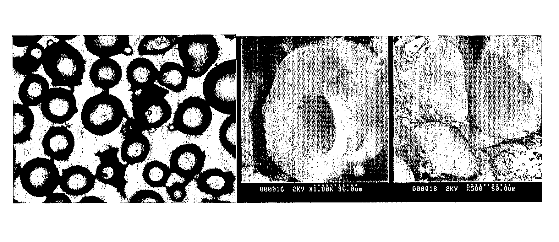
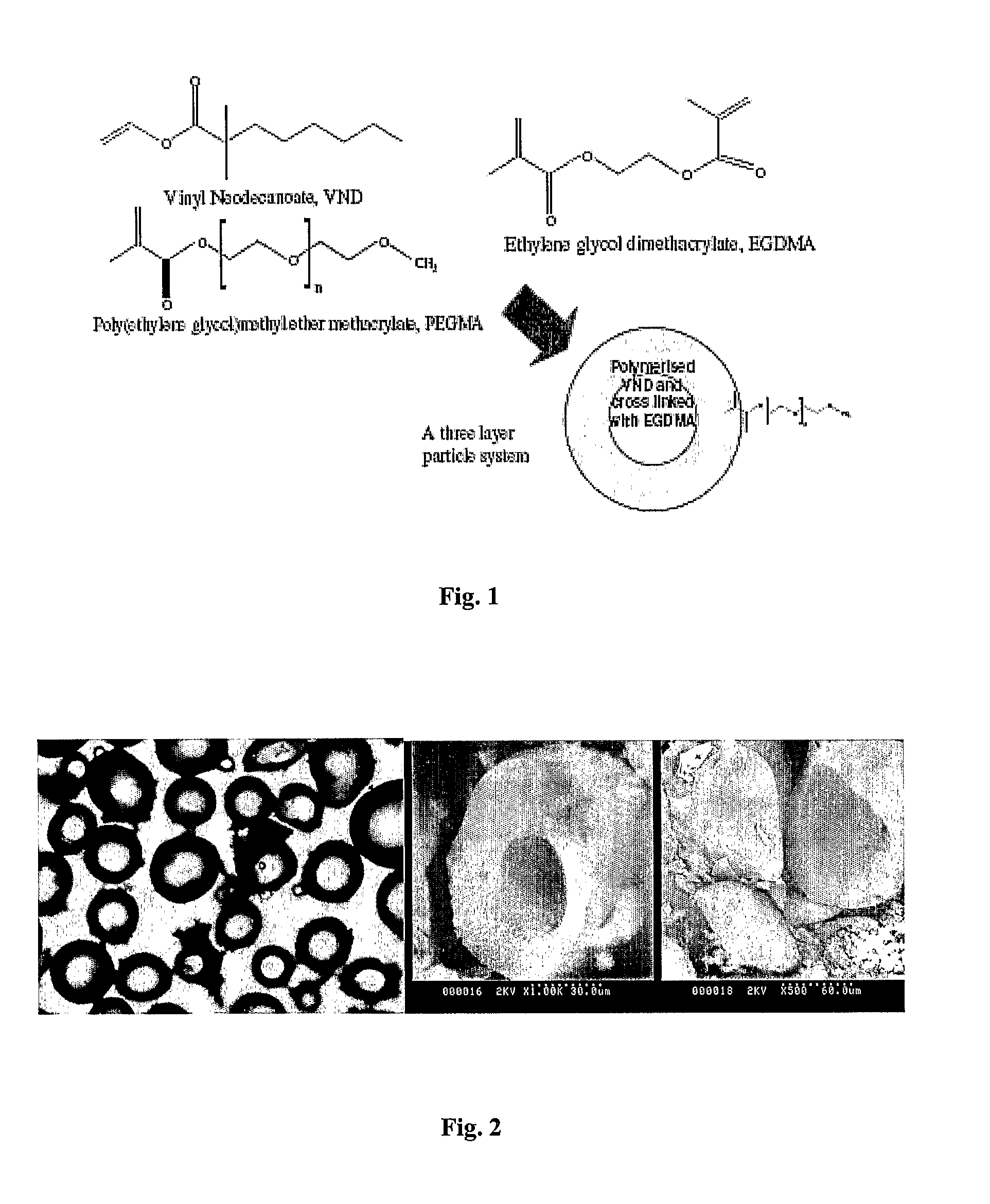
[0146]The reactor was a 250 ml wide mouth flask modified to include four 10 mm radial baffles with removable 5 neck lid. It was equipped with an overhead stirrer, 2 four bladed 40 mm turbine impeller, a condenser and an oil bath. A mixture of 1.05 g PVP and 199.5 g water was added to the reactor and purged with nitrogen with the aid of a sonicator. After the degassing and sonication step, a mixture of ethylenegycol dimethacrylate EGDMA (2.0 g), vinyl neodecanoate (8.0 g), poly(ethyleneglycol) methacrylate (1.0 g), initiator (AIBN: 0.2 g, 0.095 wt %, 2 wt % of oil phase) and butyl acetate (5.0 g) as a non-solvent was introduced to the reaction flask and degassing was continued with slow stirring at 200 rpm for another 30 minutes. Reaction was started by ramping the temperature (20° C.) from room temperature to 70° C. in 1 hour. After a reaction time of 20 hours the microspheres were filtered off and washed with water and acetone. To remove the core of the particle the particles were ...

example 2

[0147]The reactor was a 250 ml wide mouth flask modified to include four 10 mm radial baffles with removable 5 neck lid. It was equipped with an overhead stirrer, 2 four bladed 40 mm turbine impeller, a condenser and an oil bath. A mixture of 1.05 g PVP and 199.5 g water was added to the reactor and purged with nitrogen with the aid of a sonicator. After the degassing and sonication step, a mixture of ethylenegycol dimethacrylate EGDMA (5.0 g), initiator (AIBN: 0.2 g, 0.095 wt %, 2 wt % of oil phase) and butyl acetate (5.0 g) as a non-solvent was introduced to the reaction flask and degassing was continued with slow stirring at 200 rpm for another 30 minutes. Reaction was started by ramping the temperature (20° C.) from room temperature to 70° C. in 1 hour. After a reaction time of 20 hours the microspheres were filtered off and washed with water and acetone.

Results:

[0148]Three non-solvents were employed (dodecyl acetate DA, butyl acetate BA and ethyl acetate EA). While DA only resu...

example 3

Highly Crosslinked Microspheres: Formation of Poly(EGDMA) Hollow Spheres with BuAc as Solvent

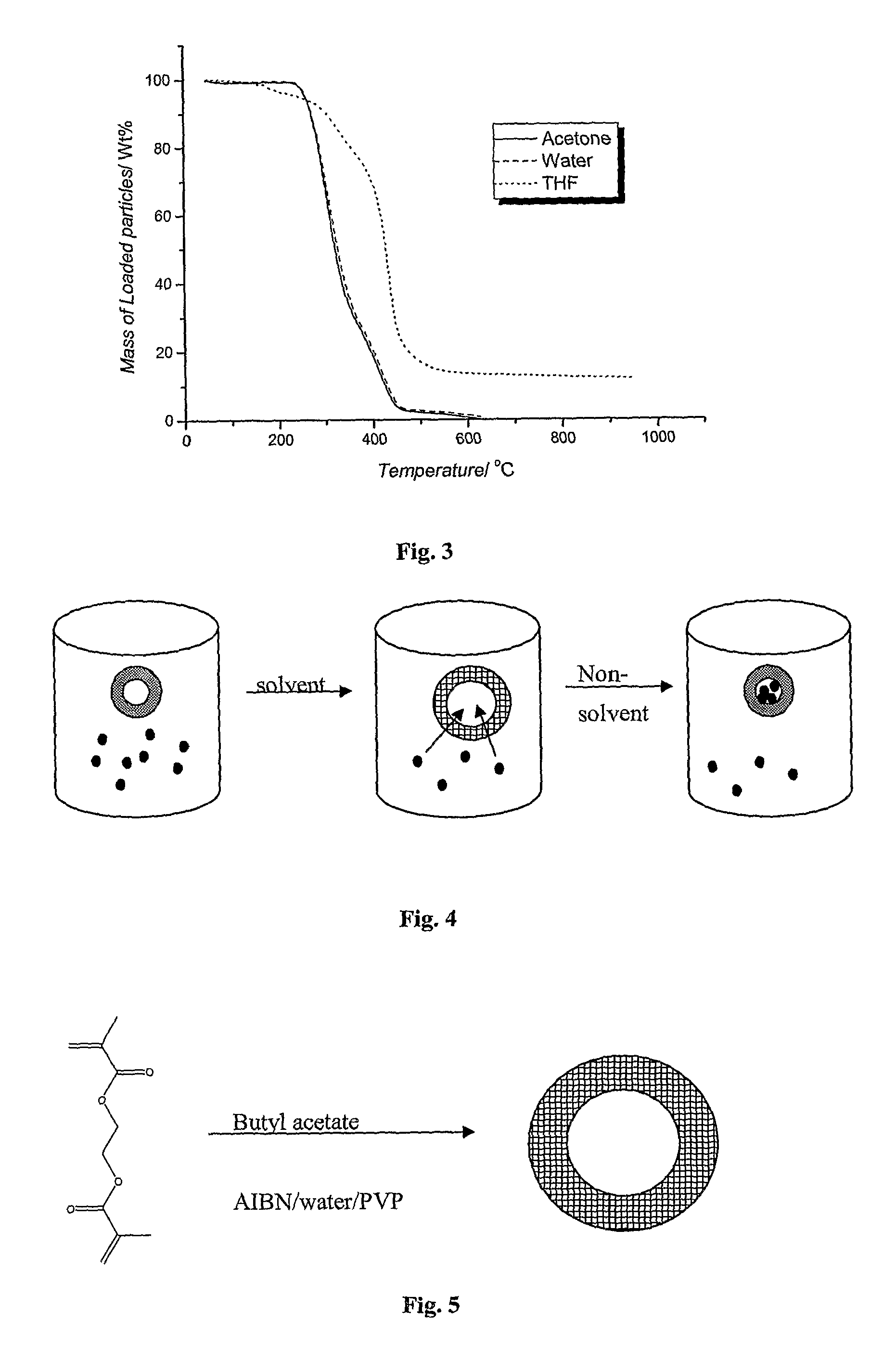
[0150]Suspension polymerization: A diagrammatic representation of the reaction is shown in FIG. 5. In a typical suspension polymerization, a 250 ml glass reactor with 5 necks was used. The reactor was modified to include four 10 mm radial baffles. The aqueous phase was prepared by dissolving 1.05 g of the stabilizer, poly(N-vinyl pyrrolidone) (PVP) in 199.5 g of distilled water. The aqueous phase was then transferred to the reactor and was purged with nitrogen with the aid of an ultrasonic tip for 30 min. The dispersed phase comprised BuAc (8.4 g), EGDMA (2.1 g) and AIBN (0.0525 g). After sonification of the aqueous phase, the dispersed phase was introduced to the reactor. Nitrogen purging was continued for another 30 min. The reaction was then allowed to proceed at 70° C. at a stirring speed of 700 rpm for a period of 20 hours. The percentage of EGDMA in the mixture with BuAc was varied in ...


PUM

PropertyMeasurementUnit
Polarityaaaaaaaaaa
Therapeuticaaaaaaaaaa
Hydrophilicityaaaaaaaaaa

Abstract

The invention provides a process for making hollow microparticles. The process comprises providing a dispersion having a continuous aqueous phase and a discontinuous organic phase and polymerising a monomer in the dispersion to form hollow polymeric microparticles. The continuous aqueous phase of the dispersion comprises a stabiliser and the discontinuous organic phase of the dispersion comprises the monomer and an organic liquid. The monomer has two or more polymerisable groups per molecule. Prior to the step of polymerising the monomer, the discontinuous organic phase does not contain a polymer.

Description

TECHNICAL FIELD[0001]The present invention relates to a process for making hollow microparticles.BACKGROUND OF THE INVENTION[0002]Hollow microparticles have a range of potential applications. The empty core allows the encapsulation of a range of material in high concentration. Possible applications therefore include drug delivery and catalysis. Microparticles are, for example, of great interest as a drug delivery system, in particular for drug administration through the hepatic artery for treatment of liver tumours.[0003]Currently hollow spheres are employed in industry as insulating materials, light-weight materials and materials with reduced electrical and heat conductivity. Most hollow spheres, especially those in industry, are processed from inorganic materials such as ceramics, TiO2, Y2O3, SiO2 and glass. (J. Breitling, J. Bloemer, R. Kuemmel, Chem. Eng. Technol. 2004, 27, 829.) Techniques to prepare these particles are manifold and range from high temperature smelting to spray...

Claims


Application Information

Patent Timeline
IPC IPC(8): A61K9/14C08J9/00C08F2/46A61K47/32A61P35/00
CPCA61K9/5026A61K9/5089A61K31/00A61K47/32C08F222/1006C08F2/48C08F218/10C08F220/26C08F2/22A61P35/00C08F222/102C08F2/10C08F2/16C08F263/06A61K9/50
Inventor TING, SEET RUI SIMON
Owner NEWSOUTH INNOVATIONS PTY LTD
Learn More