

Lithium ion secondary battery
a secondary battery and lithium ion technology, applied in the direction of cell components, final product manufacturing, sustainable manufacturing/processing, etc., can solve the problems of thermal runaway, increased battery temperature, and increased heat generation, and achieve excellent cycle performance, high capacity, and long life.
- Summary
- Abstract
- Description
- Claims
- Application Information
AI Technical Summary
Benefits of technology
Problems solved by technology
Method used
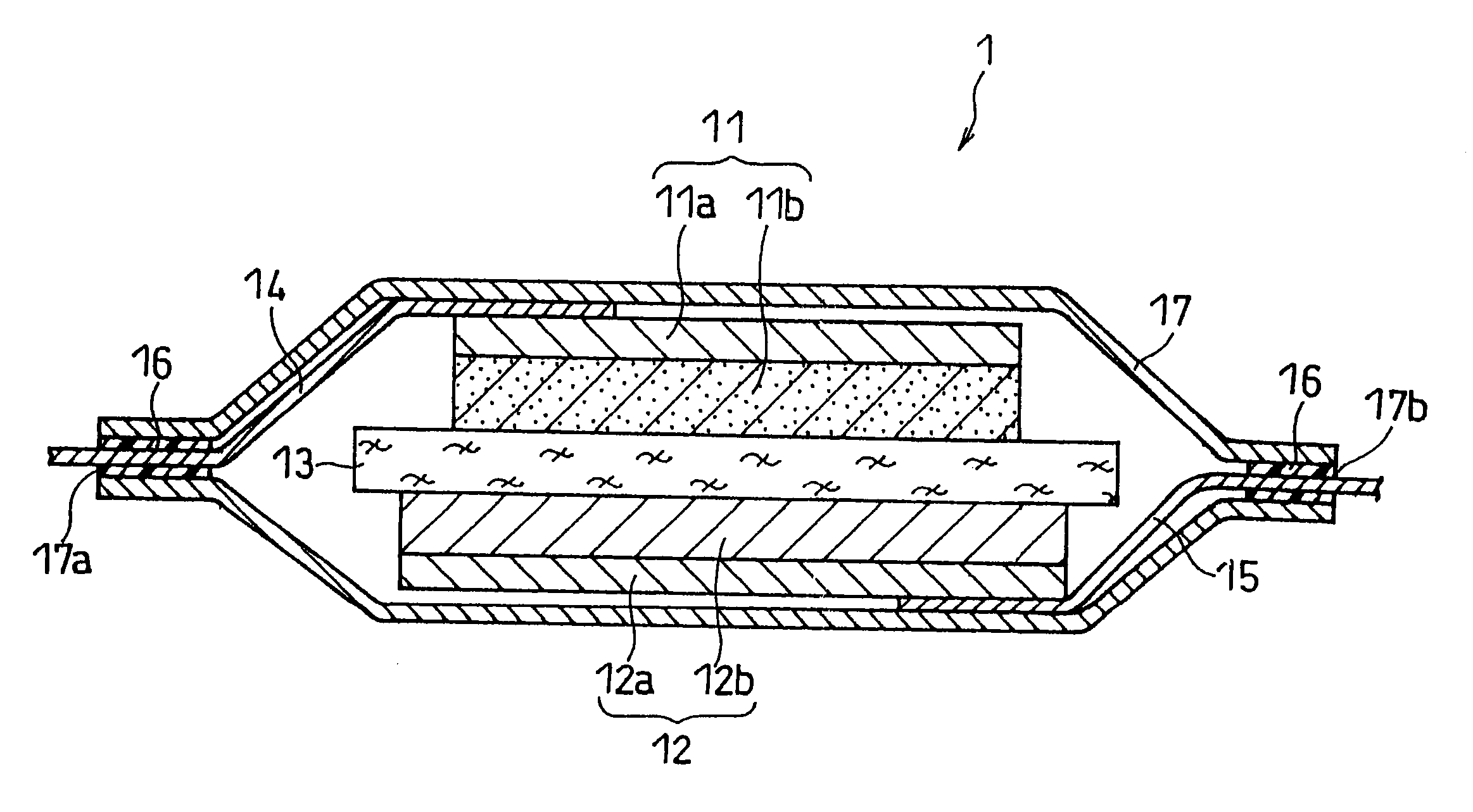
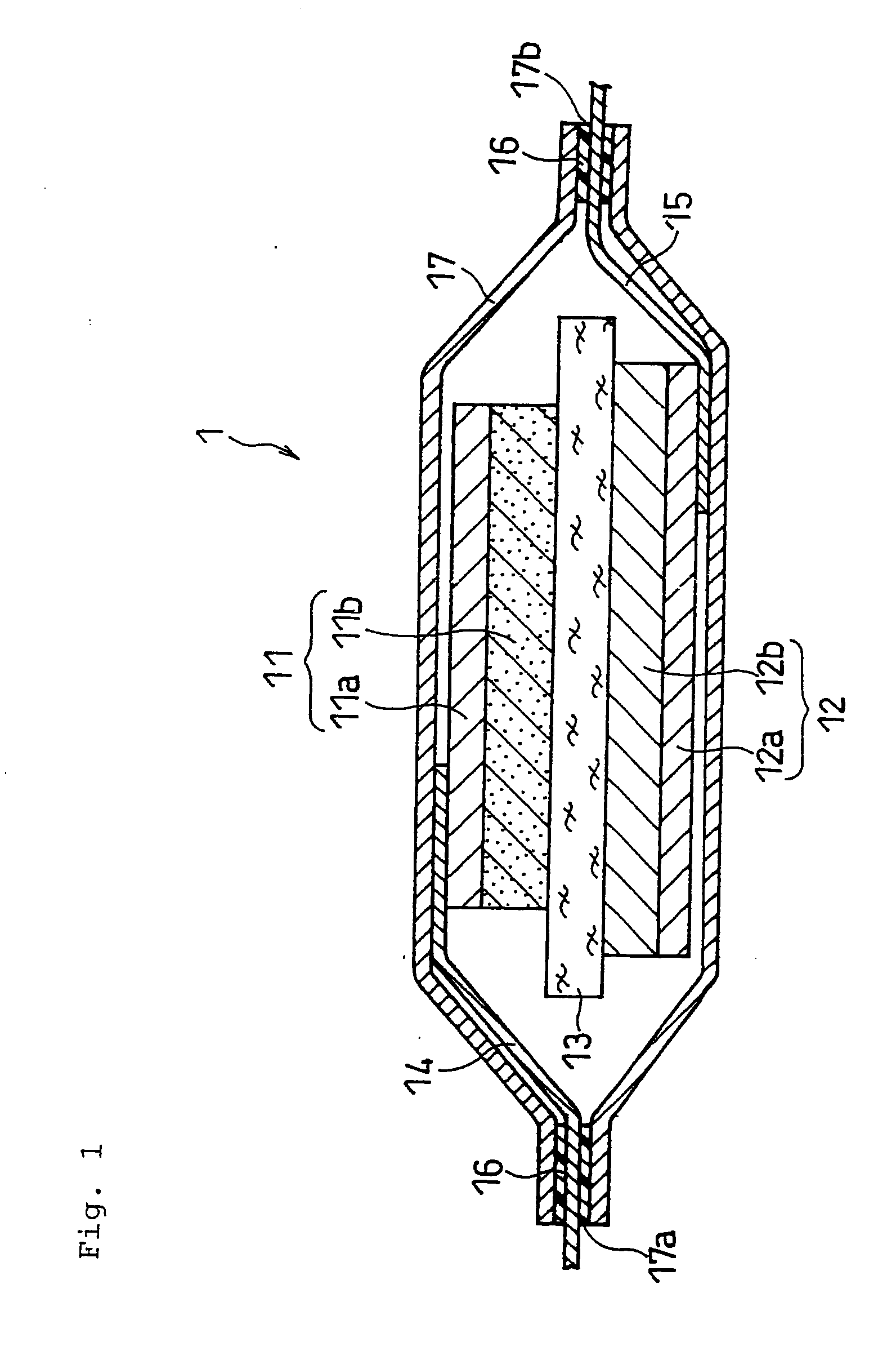
Image

Examples
example 1
(1) Positive Electrode Active Material Preparation
[0145]An aqueous solution with a metal ion concentration of 2 mol / L was prepared by adding sulfates of Co and Al in an aqueous solution of NiSO4 so that the molar ratio between Ni, Co, and Al was 7:2:1 (Ni:Co:Al=7:2:1). To this aqueous solution, a sodium hydroxide solution of 2 mol / L was dropped gradually while stirring to neutralize, thereby producing a ternary precipitate having a composition represented by Ni0.7Co0.2Al0.1(OH)2 by coprecipitation. This precipitate was separated by filtration, washed with water, and dried at 80° C., thereby obtaining a composite hydroxide. As a result of measuring the average particle size of the obtained composite hydroxide with a particle size distribution meter (product name: MT 3000, manufactured by Nikkiso Co., Ltd.), it was found that the average particle size was 10 μm.
[0146]This composite hydroxide was heated in an atmosphere at 900° C. for 10 hours for a heat treatment, to obtain a ternary ...
example 2
[0162]A lithium ion secondary battery of the present invention was made in the same manner as Example 1, except that the method for producing the negative electrode was changed as follows.
Negative Electrode Preparation
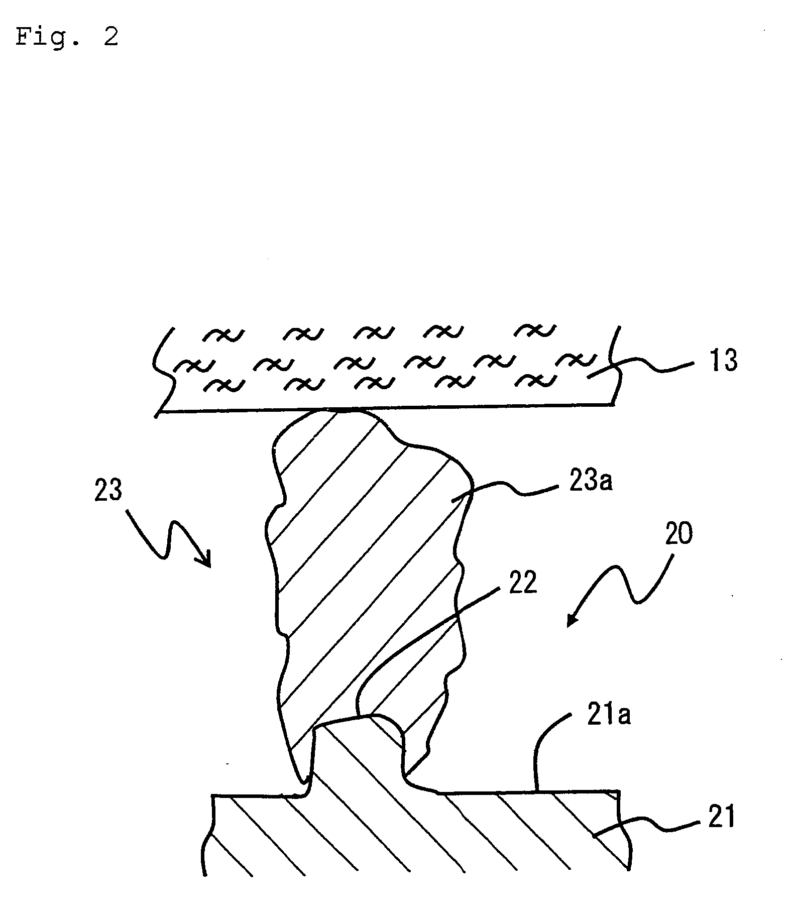
[0163]A ceramic layer with a thickness of 100 μm was formed by thermal spraying chromic oxide on the surface of an iron roll with a diameter of 50 mm. A projection-forming roll was made by forming holes, i.e., circular recess portions with a diameter 12 μm and a depth of 8 μm, on the surface of this ceramic layer by laser processing. These holes were disposed in a close-packed arrangement, with a distance between the axes of adjacent holes of 20 μm. The bottom of these holes was substantially planar at its center, and a portion connecting the periphery of the bottom with the side face is formed so as to be rounded off.
[0164]Alloy copper foil (product name: HCL-02Z, thickness 20 μm, manufactured by Hitachi Cable) containing 0.03 wt % zirconia relative to the total amoun...
experimental example 1
Battery Capacity Evaluation
[0178]For the lithium ion secondary batteries of Examples 1 to 2, and Comparative Examples 1 to 2, a cycle of charge and discharge was repeated to a total of three times under the following conditions, and a discharge capacity at the third cycles was determined. The results are shown in Table 1.
[0179]Constant Current Charge: 200 mA, End Voltage 4.2 V.
[0180]Constant Voltage Charge: End Current 20 mA, Pause Interval of 20 minutes.
[0181]Constant Current Discharge: Current 200 mA, End Voltage 2.5 V, Pause Interval of 20 minutes.
Electrode Resistance Evaluation
[0182]In the above-described battery capacity evaluation test, for the batteries after the third discharge capacity measurement, constant current charge and constant voltage charge were carried out under the same conditions as those of the capacity evaluation test. The battery after charge was disassembled, and the negative electrode was taken out and washed with a solvent (dimethyl carbonate). The negativ...
PUM
| Property | Measurement | Unit |
|---|---|---|
| melting temperature | aaaaa | aaaaa |
| pressure | aaaaa | aaaaa |
| thickness | aaaaa | aaaaa |
Abstract
Description
Claims
Application Information