Solid fuel volatilization to produce synthesis gas

a technology of solid fuel and volatilization, which is applied in the direction of combustible gas production, physical/chemical process catalysts, bulk chemical production, etc., can solve the problems of complex overall reaction, deactivation and poisoning of most gasification catalysts, and limited process capital costs of traditional btl equipment, etc., to achieve high selectivity, small and simple processes

Active Publication Date: 2010-08-12
RGT UNIV OF MINNESOTA
View PDF15 Cites 18 Cited by
  • Summary
  • Abstract
  • Description
  • Claims
  • Application Information

AI Technical Summary

Benefits of technology

[0014]Embodiments of the present invention provide a unique catalytic method to convert nonvolatile biomass to synthesis gas (syngas) without an external heat source and at least an order of magnitude faster than existing systems. Solid biomass directly contacting a hot catalytic surface maintained by heat conduction from partial oxidat

Problems solved by technology

The capital costs of traditional BTL equipment has restricted the processes to large scales (˜400 MWth) demanding an abundant, local supply of biomass.
Most gasification catalysts exhibit deactivation and poisoning due to the development of surface carbon (coke) and char and the condensation of inorganic ash.
Back-face catalyst bed temperatures were not used due to significant temperature gradients, resulting from heat conduction to the monolith support.
The chemical and heat integration of the two processes expands the complexity of the overall reaction such that mechanistic observations are currently only available through effluent data and experiments considering more simple fuel species.
The magnitude of particle conversion occurring within the gaseous region 3-10 mm above the catalytic bed is likely limited, because previous examination has measured the gas-phase temperature of this region less than 300° C. severely limiting particle conversion by pyrolysis.

Method used


Image

  • Solid fuel volatilization to produce synthesis gas
  • Solid fuel volatilization to produce synthesis gas
  • Solid fuel volatilization to produce synthesis gas

Examples


example 1

Experimental Reactor System

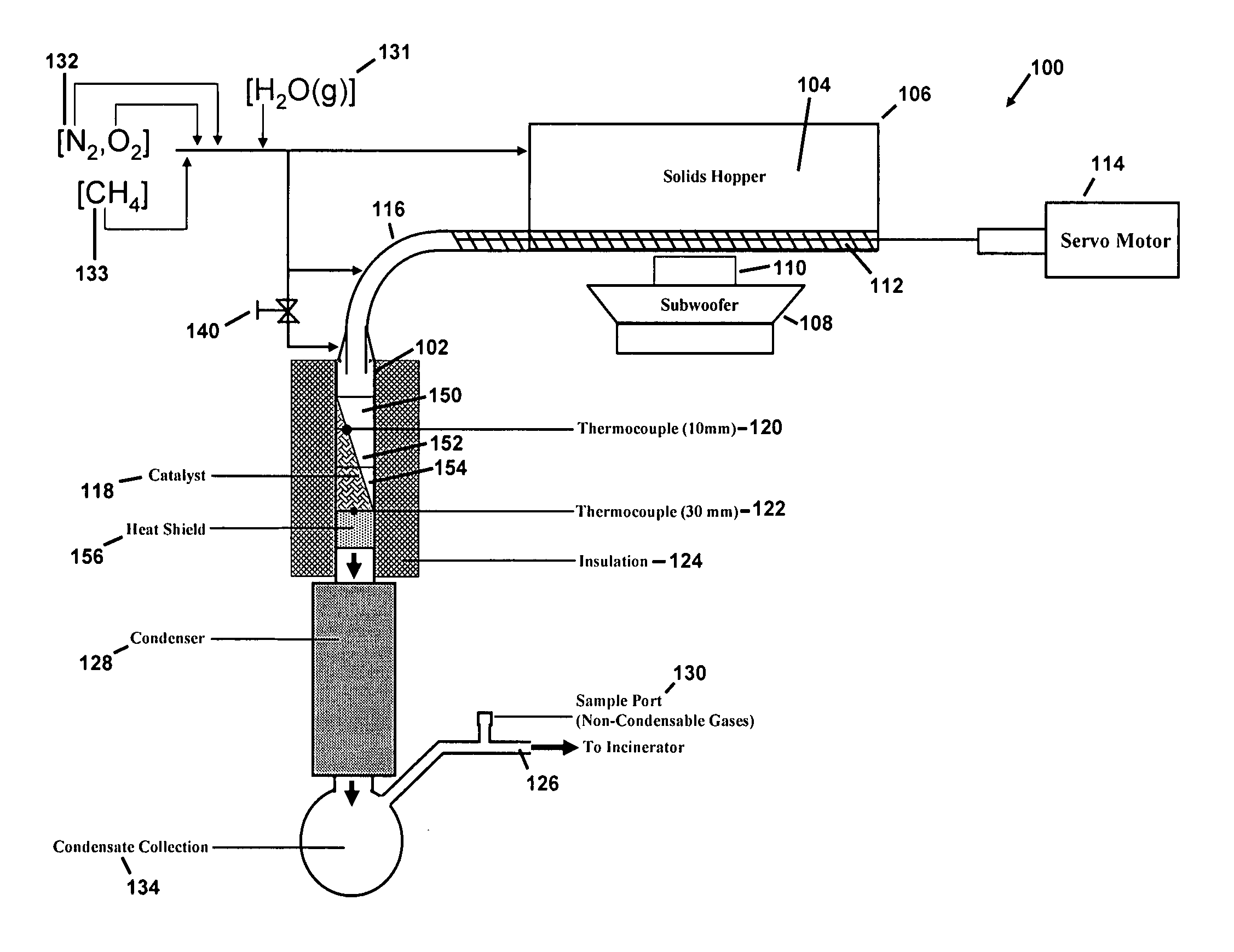
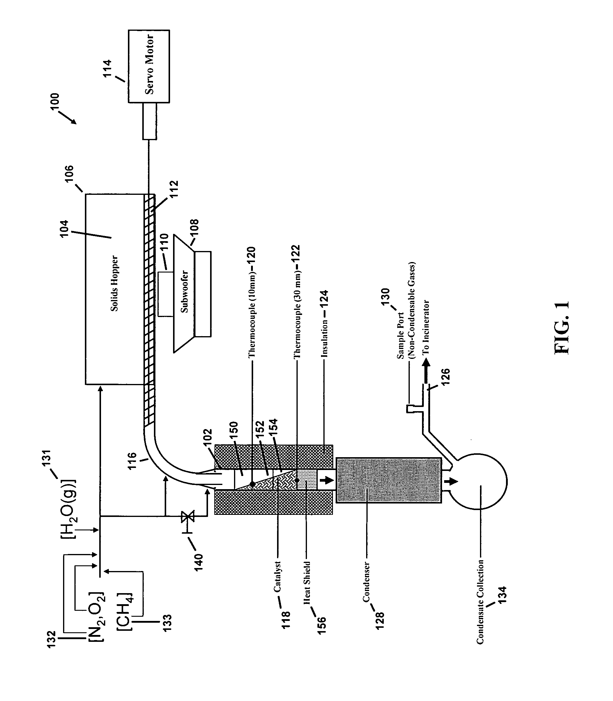
[0063]The reactor system 100 consisted of a reactor 102, which is a custom-made quartz tube of 19 mm inner diameter as shown in FIG. 1. The reactor 102 was glass blown by a glass worker at University of Minnesota and shaped using material made by Chemglass, Inc., having offices in Vineland, N.J. Approximately one (1) kg of solids 104 were loaded into a two liter solids hopper 106 and vibrated by a Sony Active subwoofer 108 Model no. SA-WM250 made by Sony Corporation having offices in New York, N.Y. The subwoofer 108 was connected to a GT0804 speaker 110 made by JBL, Inc. having offices in Woodbury, N.Y.

[0064]The solids 104 were moved to the reactor system 100 with use of a solid screw auger 112, i.e., a Servodyne brand mixer made by Cole-Parmer Instrument Co., having offices in Vernon Hills, Ill. Use of a subwoofer 108 and speaker 110 helped to prevent particle aggregation and also served to fill the solid screw auger 112 to capacity. The solid screw auger...

example 2

[0079]Additional experiments with various solid fuels were performed using the reactor described in Example 1. The specific procedure and starting materials are described below.

[0080]Methods. All experiments were conducted over Rh-based catalysts with a Ce additive on α-Al2O3 supports 17 mm in diameter and 10 mm in length consisting of either 45 or 80 pores per inch. A slurry of γ-Al2O3 washcoat has been added drop-wise, dried, and heated to 600° C. for 6 hrs where indicated before catalyst impregnation. Catalysts were prepared by the incipient wetness technique using aqueous solutions of Rh(NO3)3 and Ce(NO3)3.6H2O resulting in loadings of 2.5 wt % of the alumina support for each metal. Dried catalysts were calcined at 600° C. for 6 hrs in air. The quartz reactor tube as described in Example 1 was loaded with three catalyst-impregnated supports and a fourth 80 ppi blank alumina support wrapped in ceramic paper to prevent gas bypass. K-type thermocouples were inserted after the first...

example 3

[0097]This prophetic example provides additional variations that may be used in conjunction with the methods described in Examples 1 and / or 2. Variations in procedure may be necessary depending on the type of solid fuel being tested. For example, for solids with low melting points, the feed system should prevent melting in the metering device. This could be done using a heat exchanger as a water cooler.

[0098]Testing can further be done with other forms of materials. For example, to determine the effect of lignin, a three-dimensional polymer of phenyl-propane monomers, on carbohydrate processing, a cellulose sample containing 25 wt % lignin can be separated from Aspen wood chips by soda pulping.

[0099]In order to test directly with Aspen chips, a strategy for handling the approximately 0.5% ash can be used. The ash, of which the minerals Ca, K, and Mg make up over 90% in the form of oxides and carbonates, exhibits very low vapor pressure. [10] These nonvolatile components can be remov...


PUM

PropertyMeasurementUnit
Temperatureaaaaaaaaaa
Timeaaaaaaaaaa
Residence timeaaaaaaaaaa

Abstract

A method comprising contacting a carbon and hydrogen-containing solid fuel and a metal-based catalyst in the presence of oxygen to produce hydrogen gas and carbon monoxide gas, wherein the contacting occurs at a temperature sufficiently high to prevent char formation in an amount capable of stopping production of the hydrogen gas and the carbon monoxide gas is provided. In one embodiment, the metal-based catalyst comprises a rhodium-cerium catalyst. Embodiments further include a system for producing syngas. The systems and methods described herein provide shorter residence time and high selectivity for hydrogen and carbon monoxide.

Description

CROSS-REFERENCE TO RELATED APPLICATIONS[0001]This application claims priority under 35 U.S.C. §119(e) to U.S. Provisional Patent Application No. 60 / 893,080, filed Mar. 5, 2007, which is incorporated herein by reference in its entirety.GOVERNMENT SUPPORT[0002]This invention was made with government support under Grant Number DE-FG02-88ER13878 from the U.S. Department of Energy. The United States Government has certain rights in the invention.BACKGROUND[0003]Dependence on petroleum and continued carbon emissions have led to a focus on methods of utilizing a large supply of biomass, such as non-fossilized biomass in the form of grasses, trees, and agricultural residue as alternative energy sources [1]. However, biomass, including fossilized biomass (e.g., petroleum), presents a significant processing challenge, because it is a complex mixture of biopolymers of low energy density dispersed across the countryside. Biomass is typically used to produce synthesis gas (syngas), which, in tur...

Claims


Application Information

Patent Timeline
IPC IPC(8): C01B3/38B01J19/00
CPCB01J23/63Y02E50/30B01J37/0201C01B3/12C10J3/26C10J2200/158C10J2300/0916C10J2300/0946C10J2300/0959C10J2300/0986C10J2300/1846C10L5/363C10L5/44Y02E50/10B01J35/04Y02P20/145Y02P20/52
Inventor SCHMIDT, LANNY D.DAUENHAUER, PAUL J.DEGENSTEIN, NICK J.DREYER, BRADON J.COLBY, JOSHUA L.
Owner RGT UNIV OF MINNESOTA
Why Eureka
Try Eureka