Battery separator and battery using the same

a battery separator and separator technology, applied in the direction of cell components, final product manufacturing, sustainable manufacturing/processing, etc., can solve the problems of increasing the internal resistance of the battery, the isal pressure for maintaining the electrical connection between the separator and each electrode cannot be sufficiently applied to the electrode surface, and the battery container of the laminated-film type cannot be maintained. , to achieve the effect of excellent oxidation resistance, high oxidation resistance, and excellent oxidation resistan

Active Publication Date: 2011-06-09
NITTO DENKO CORP
View PDF8 Cites 6 Cited by
  • Summary
  • Abstract
  • Description
  • Claims
  • Application Information

AI Technical Summary

Benefits of technology

[0033]The battery separator of the invention is obtained by supporting on a porous substrate a layer of a crosslinked polymer obtained by reacting a reactive polymer having, in the molecule thereof, a first reactive group containing active hydrogen and a second reactive group having cationic polymerizability with a polycarbonate urethane prepolymer terminated by an isocyanate group. The crosslinked polymer hence has excellent oxidation resistance and further has adhesiveness to electrodes.
[0034]Consequently, this battery separator can be adhered to electrodes by stacking the electrodes on the separator to obtain an electrode/separator stack; introducing the stack into a battery container; and subsequently pouring a nonaqueous electrolyte solution containing a cationic polymerization catalyst into the battery container to cause at least part of the crosslinked polymer on the porous substrate to swell around the interface between the crosslinked polymer and the electrode(s) and to penetrate into the electrode active material(s) together with the electrolyte solution and, simultaneously therewith, to cationically polymerize and further crosslink the crosslinked polymer, thereby causing the electrolyte solution to partially gel at least around the interface be

Problems solved by technology

Compared with the conventional metallic can cases, battery containers of the laminated-film type have a drawback that an areal pressure for maintaining electrical connection between the separator and each electrode cannot be sufficiently applied to electrode surfaces.
Because of this, these battery containers have a problem that the distance between the electrodes partly increases with the lapse of time due to the expansion/contraction of the electrode active materials during battery charge/discharge, resulting in an increase in the internal resistance of the battery and hence in a decrease in battery characteristics.
In addition, there is a problem that unevenness of resistance occurs in the battery and this also reduces battery characteristics.
In the case of producing a sheet-form battery having a large area, there has been a problem that the distance between the electrodes cannot be kept constant and the internal resistance of the battery becomes uneven, making it impossible to obtain sufficient battery characteristics.
However, those processes have had the following problem.
Consequently, sufficient cycle characteristics and sufficient high-rate discharge characteristics cannot be obtained.
As a result, there is a concern that the separator might thermally contract to cause short-circuiting between the electrodes.
In addition, although the adhesive resin in the battery is in the state of being swollen with the electrolyte solution, th

Method used


Image

  • Battery separator and battery using the same
  • Battery separator and battery using the same
  • Battery separator and battery using the same

Examples


reference example 1

Preparation of Electrode Sheets

[0106]Eighty-five parts by weight of lithium cobalt oxide (Cellseed C-10, manufactured by Nippon Chemical Industrial Co., Ltd.) as a positive-electrode active material was mixed with 10 parts by weight of acetylene black (Denka Black, manufactured by Denki Kagaku Kogyo K.K.) as a conduction aid material and 5 parts by weight of a vinylidene fluoride resin (KF Polymer L #1120, manufactured by Kureha Chemical Industry Co., Ltd.) as a binder. This mixture was slurried with N-methyl-2-pyrrolidone so as to result in a solid concentration of 15% by weight. This slurry was applied in a thickness of 200 μm to an aluminum foil having a thickness of 20 μm (current collector) and vacuum-dried at 80° C. for 1 hour and then at 120° C. for 2 hours. The coated foil was pressed with a roller press to prepare a positive-electrode sheet having an active-material layer with a thickness of 100 μm.

[0107]Eighty parts by weight of mesocarbon microbeads (MCMB 6-28, manufactur...

reference example 2

Production of Porous Polyethylene Resin Film

[0108]Fifteen parts by weight of ultrahigh-molecular polyethylene having a weight-average molecular weight of 1,000,000 (melting point, 137° C.) was evenly mixed with 85 parts by weight of liquid paraffin to obtain a slurry. This slurry was melt-kneaded with a twin-screw extruder at a temperature of 170° C. and extruded through a coathanger die into a sheet having a thickness of 2 mm. The resultant sheet was cooled while being taken off with a roll. Thus, a gel sheet having a thickness of 1.3 mm was obtained. This gel sheet was subjected at a temperature of 123° C. to simultaneous biaxial stretching in which the sheet was stretched in the MD (machine direction) 4.5 times and in the TD (transverse direction) 5 times. Thus, a stretched film was obtained.

[0109]Decane was used to remove the liquid paraffin from the stretched film. Thereafter, the film was dried at room temperature to remove the decane. Thus, a porous film was obtained. The por...

reference example 3

Preparation of Reactive Polymer

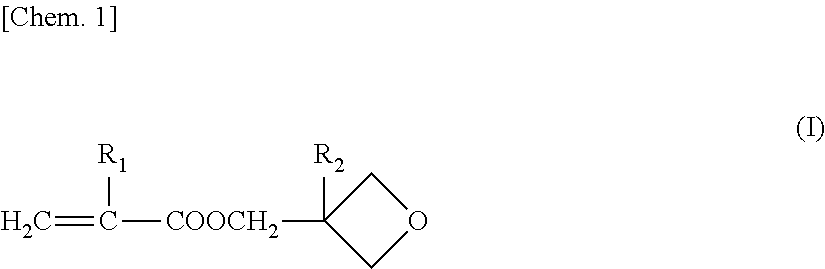
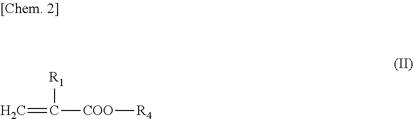
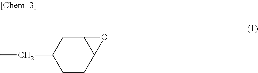
[0118]Into a three-necked flask having a capacity of 500 mL and equipped with a reflux condenser were introduced 60 g of methyl methacrylate, 1.0 g of 3,4-epoxycyclohexylmethyl methacrylate, 24 g of 3-ethyl-3-oxetanylmethyl methacrylate, 0.84 g of 4-hydroxybutyl acrylate, 14.16 g of 2-methoxyethyl acrylate, 25 g of ethyl acetate, and 0.20 g of N,N′-azobisisobutyronitrile. While nitrogen gas was being introduced, the contents were stirred and mixed for 30 minutes and then heated to 70° C. to initiate radical polymerization. At the time when about 1 hour had passed, an increase in the viscosity of the reaction mixture was observed. Thereafter, while ethyl acetate was being added to the reaction mixture, the temperature was kept almost constant and the polymerization was continued for further 8 hours.

[0119]After completion of the reaction, the reaction mixture obtained was cooled to 40° C., and ethyl acetate was added thereto. The contents were stirred an...


PUM


Abstract

The present invention relates to a battery separator including: a porous substrate; and a layer of a crosslinked polymer supported on at least one surface of the porous substrate, in which the crosslinked polymer is obtained by reacting (a) a reactive polymer having, in the molecule thereof, a first reactive group containing active hydrogen and a second reactive group having cationic polymerizability with (b) a polycarbonate urethane prepolymer terminated by an isocyanate group.

Description

TECHNICAL FIELD[0001]The present invention relates to a battery separator and a battery using the separator. More particularly, the invention relates to a battery separator obtained by supporting a layer of a crosslinked polymer having a polycarbonate urethane framework on a porous substrate, and relates to a battery using the separator.BACKGROUND ART[0002]Lithium ion secondary batteries having a high energy density are extensively used in recent years as power sources for small portable electronic appliances such as cell phones and notebook type personal computers. Such a lithium secondary battery is produced through the steps of stacking or winding sheet-form positive and negative electrodes together with, for example, a porous polyolefin resin film, introducing the resultant stack into a battery container constituted of, for example, a metallic can, subsequently pouring an electrolyte solution into the battery container, and tightly sealing the opening of the battery container.[0...

Claims


Application Information

Patent Timeline
IPC IPC(8): H01M2/16H01M10/058H01M10/04H01M10/0566H01M50/417H01M50/449
CPCH01M2/1653H01M2/1673H01M2/1686Y10T29/4911H01M10/058Y02E60/122Y10T29/49108H01M10/0525Y02P70/50Y02E60/10H01M50/46H01M50/449H01M50/417H01M50/414H01M50/491H01M10/38H01M10/052H01M10/0565H01M2300/0082
Inventor NOUMI, SHUNSUKETAKE, HIROYOSHISHO, KINKOU
Owner NITTO DENKO CORP
Why Eureka
Try Eureka