
Heat ray reflective film and laminate thereof, and coating fluid for forming heat ray reflective layer

Inactive Publication Date: 2011-10-27
MITSUBISHI CHEM CORP
View PDF7 Cites 42 Cited by
  • Summary
  • Abstract
  • Description
  • Claims
  • Application Information

AI Technical Summary

Benefits of technology

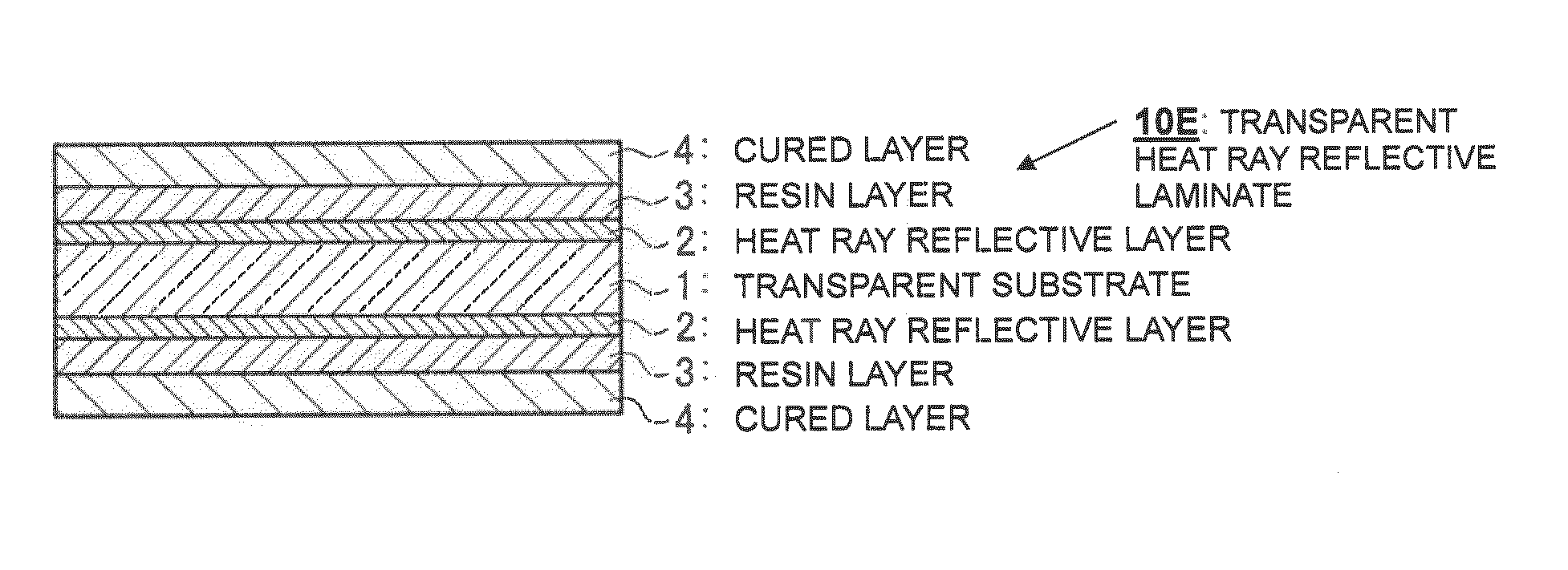
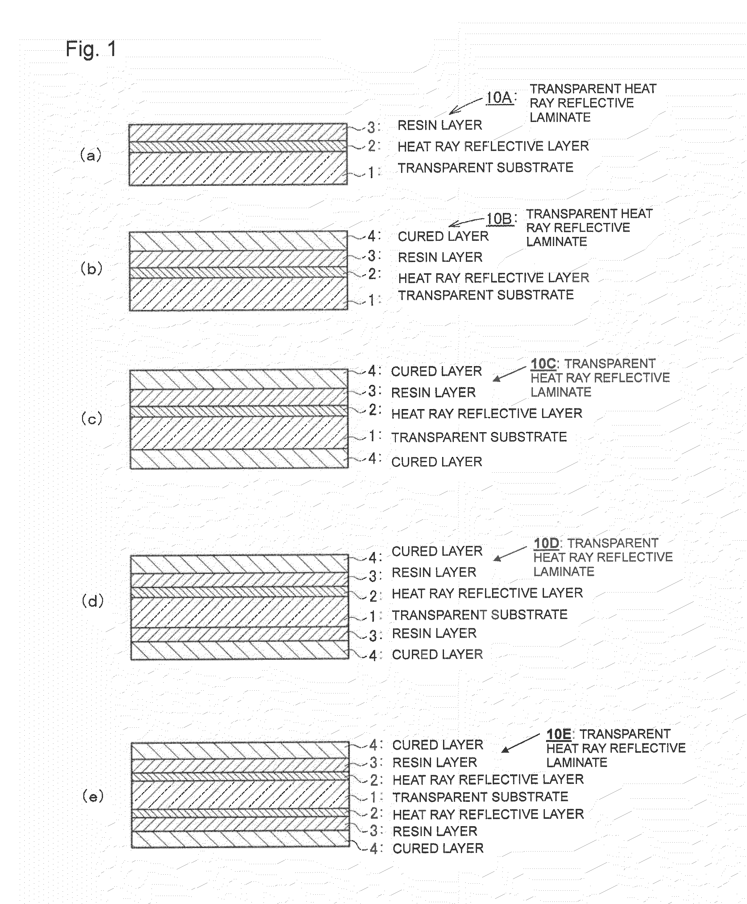
[0036]By the heat ray reflective laminate of the present invention, it is possible to provide a transparent shielding component which has a high heat ray reflectivity and which has high environmental durability and is excellent in the cost performance. Further, by carrying out formation of the respective layers by a wet film-forming method, it is possible to impart a heat-shielding performance even to a transparent component having a large size and a curved surface, and particularly, by applying it to a window material, it is possible to improve the comfort in a room or vehicle and to accomplish energy saving by reducing the load on an air conditioner.
[0037]Particularly when as a transparent substrate, a transparent resin substrate is employed and applied to a grazing component for an automobile, it is possible to accomplish a substantial improvement of the gasoline mileage due to weight reduction of an automobile and reduction of the load for an air conditioner.
[0038]Further, when it is used as such a window material, by incorporating a component having an ultraviolet absorbing group to a laminate-constituting layer, it is possible to prevent the deterioration by ultraviolet rays.
[0039]Further, by the heat ray reflectivity, it is possible to prevent the deterioration by a heat formed by the heat ray absorption of the transparent substrate.
[0040]Whereas, the metal film for heat ray reflection of the present invention has a high heat ray reflectivity, and it is thereby possible to relatively control the visible light absorption and the visible light reflection and to realize a heat ray reflecting film excellent in heat stability in a single layer structure. By using such as a metal film for heat ray reflection, it is possible to provide a heat ray reflective laminate which is free from an adverse effect of non-uniformity of the film thickness over the appearance. It is thereby possible to easily impart a heat ray shielding function even to a transparent substrate having a large size and a curved surface, without impairing the appearance. Further, by forming such a heat ray reflective layer by a wet film-forming method, reduction of the cost becomes possible.
[0041]Further, the present invention provides a heat ray reflective film which has a high heat resistance and a low solar absorbance and which selectively reflects infrared ray as compared with visible light and is excellent in moist heat resistance, and a laminate having such a heat ray reflective film formed on a transparent substrate.

Problems solved by technology

However, in the case of absorbing heat rays, the absorbed wavelength light changes to heat, which, as a radiation heat, warms up the inside of car or room, whereby the heat ray shielding ability is poor.
Further, as the absorbed light changes to heat, deterioration of the transparent component is likely to be accelerated.
Further, in a case where an organic dye is employed, the durability of the dye itself is likely to be questionable.
In addition, such an organic dye has an absorption wavelength also in a visible light region, whereby coloring becomes problematic from the viewpoint of the appearance.
However, an ultrathin metal film has a problem with respect to the durability, and an ultrafine film formed by a vapor deposition method or a sputtering method has a high activity at its metallic interface and is likely to undergo aggregation or oxidation.
However, such methods have a problem such that an interference occurs against light with a specific wavelength by the covering with the protective layer, and depending upon the film thickness or the viewing angle, the film looks as if it is colored to have a specific color.
Further, the film-forming is an operation to be carried out all in a vacuum environment, such being problematic from the viewpoint of the productivity or costs.
However, in such a method, it is possible that the fluorescent whitener and the ultraviolet absorber are likely to bleed out during the use for a long period of time.
However, the protective film to be formed by electron beam vapor deposition has a problem from the viewpoint of costs, and further, in a case where an overcoating is further applied thereon, a problem remains from the viewpoint of the adhesion.
On the other hand, in the case of employing a thermosetting varnish, due to shrinkage upon curing, a strain is likely to result between it and the electromagnetic wave shielding layer, and in a case where an overcoating is further applied thereon, a problem remains again from the viewpoint of the adhesion.
These problems may not be substantial problems in an application to displays, but become serious in an application to a window material where higher durability is required.
However, such a method has a problem of peeling of the protective layer caused by an internal strain formed at an interface between the heat ray reflective layer and the protective layer due to shrinkage upon curing of the silicate, a problem of brittleness of the silicate, and further a problem of deterioration of the heat ray reflective layer due to a hydrophilic action inherent to the silicate.
Further, in order to form a dense silicate film, treatment at a high temperature is required, and in such a forming process, the heat ray reflective layer may be destroyed.
Such a problem relating to deterioration of the heat ray reflective layer has been solved by coating silver nanoparticles with gold, but such brings about a new problem of cost up, and further, the above-mentioned peeling problem has not yet been solved.
Under these circumstances, it has been considered difficult to obtain a transparent heat ray reflective laminate excellent in durability.
In a case where it is used as a window material, if coating defects such as aggregates are present in the heat ray reflective layer formed by coating, they may impair the appearance.
For example, in a case where the binder resin to be used for a heat ray reflective layer has a too strong interaction with metal particles constituting the heat ray reflective layer, aggregates will be formed, and coating defects may result in the coating step.
Further, in the film-forming process for the heat ray reflective layer, fusion of metal particles to one another is likely to be prevented, whereby no adequate heat ray reflective performance may be obtainable.
However, due to deterioration of such a dispersant or growth of fine silver particles, the storage stability of the coating fluid is likely to be deteriorated.
Further, in a case where electrical conductivity or heat ray reflectivity is to be secured by applying a liquid containing fine metal particles, silver is mainly employed as a metal species, in many cases, but silver has a serious problem from the viewpoint of the durability.
Further, with a thin film of silver, an environmental load such as salt water is likely to bring about deterioration of the appearance or performance.
However, a heat ray shielding film is mainly used for an application as a window material for buildings or automobiles and thus is exposed to a corrosive environment severer than a transparent electroconductive film, and therefore, higher deterioration durability capable of being durable against it, is required.
Here, the coating defects may be a “missing” resulting when the coating fluid is repelled from the substrate, or aggregates resulting from aggregation of a component contained in the coating fluid such as fine metal particles.
Around such coating defects, smoothness or uniformity of the thin metal film is substantially deteriorated, and therefore, even if a protective layer is formed by a transparent resin on the thin metal film, the coating defects are likely to be starting points for deterioration of the film under a severe corrosion environment.
In spite of such requirements for a heat ray shielding film, the technique in the Patent Document 7 is not applicable to the formation of a thin film because of the form being a paste, although it is possible to obtain an effect to prevent corrosion of fine metal particles, and it is not possible to solve the deterioration starting from the coating defects in the thin metal film.
Whereas, by the technique of the Patent Document 8, a highly hydrophobic compound such as an alkanethiol is added to a coating fluid, whereby dispersion stability of the fine metal particles tends to deteriorate, and aggregates are likely to be formed in the thin metal film to be formed, or an alkanethiol is bonded to fine metal particles, whereby the surface of fine metal particles is covered with long chain alkyl groups, whereby fusion of fine metal particles in the firing process is likely to be impaired, and it is not possible to obtain a thin metal film having a sufficient heat ray shielding ability.
However, a surfactant has a nature to be strongly adsorbed to fine metal particles, and if the amount of a surfactant to be incorporated is large, the major portion of the surface of the fine metal particles will be covered by the surfactant, whereby fusion of the fine metal particles during firing treatment tends to be impaired.
Further, a surfactant has a hydrophilic moiety in its molecular structure and is capable of holding moisture, whereby when incorporated in a thin metal film, it is likely to induce deterioration by moisture, or it is likely to deteriorate the adhesion when a laminate is prepared.
Thus, it is not advisable to add a surfactant to a coating fluid for a heat ray shielding film.

Method used


Image

  • Heat ray reflective film and laminate thereof, and coating fluid for forming heat ray reflective layer
  • Heat ray reflective film and laminate thereof, and coating fluid for forming heat ray reflective layer
  • Heat ray reflective film and laminate thereof, and coating fluid for forming heat ray reflective layer

Examples


examples

[0500]Now, the present invention will be described in further detail with reference to Examples, but it should be understood that the present invention is by no means restricted to the following Examples.

[0501]Here, the evaluations of the heat ray reflective metal film (the same as the heat ray reflective layer or the heat ray reflective film) and the heat ray reflective laminate were carried out by the following methods.

[0502]The thickness of the heat ray reflective metal film (the heat ray reflective layer) was, when the substrate was glass, evaluated by means of a step / surface roughness / fine shape-measuring apparatus (P15, manufactured by KLA Tencor) from the step when a part of a sample was scraped off. The measuring conditions were such that the measured length was 1 mm, the scanning rate was 10 μm / sec, and the needle pressure was 0.2 mg.

[0503]The thickness of the heat ray reflective metal film (the heat ray reflective layer) was, when the substrate was a resin, evaluated by me...

example i-1

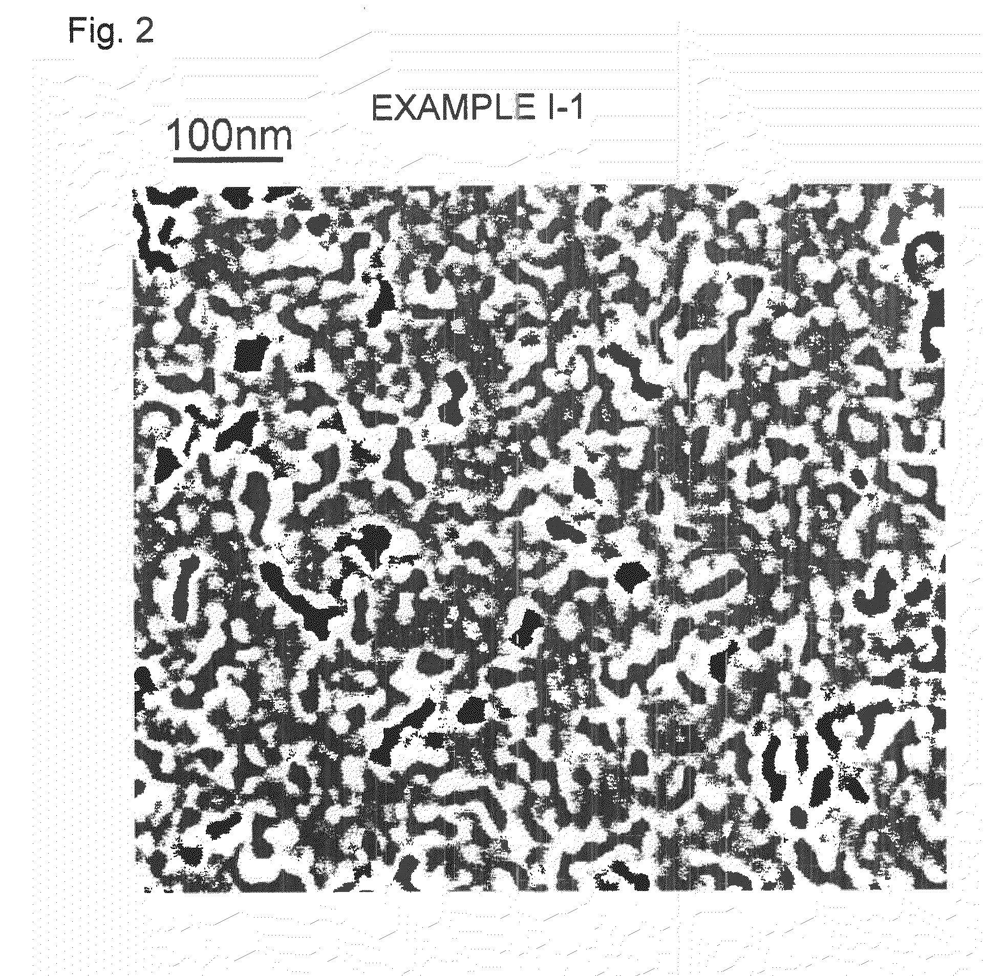
[0554]11.9 Parts by weight of a silver colloid aqueous solution(average particle size evaluated by a dynamic light scattering method: 23 nm, solid content concentration: 3.6 wt %, pH 5.1, citric acid content: 2.1 wt %) and 0.09 part by weight of a 3 wt % polyvinyl alcohol aqueous solution (“PVA117”, manufactured by Kuraray Co., Ltd., degree of polymerization: 1,700, Tg=83° C.) were mixed to prepare coating fluid 1-A.

[0555]0.8 mL of coating fluid I-A was dropped on a slide glass (manufactured by Matsunami Glass Ind., Ltd., substrate size: 76 mm×26 mm, thickness: 1.3 mm, solar absorptance: 6%, surface roughness: 0.2 nm) and applied by a spin coater (“1H-D7”, manufactured by Mikasa Co., Ltd.) under a condition of 500 rpm for 30 seconds, followed by heat-drying for 10 minutes on a hot plate (“HPD-3000”, manufactured by As One Corporation) at 70° C. Then, heat-drying was carried out for 10 minutes in a constant temperature dryer (“DO-450FPA”, manufactured by As One Corporation) at 150° C...

example i-2

[0556]Coating fluid I-B was prepared by carrying out the same operation as in Example I-1 except that the silver colloid aqueous solution was changed to 29.0 parts by weight, and the 3 wt % polyvinyl alcohol aqueous solution was changed to 1.0 part by weight.

[0557]Heat ray reflective metal film I-B was prepared by carrying out the same operation as in Example I-1 except that coating fluid I-B was used, and the time for heat-treatment at 150° C. after drying at 70° C. was changed to 30 minutes, and various evaluations were carried out. The evaluation results of heat ray reflective metal film I-B are shown in Tables 2a and 2b. Further, an SEM photograph of heat ray reflective metal film I-B is shown in FIG. 3.


PUM

PropertyMeasurementUnit
Temperatureaaaaaaaaaa
Lengthaaaaaaaaaa
Fractionaaaaaaaaaa

Abstract

Disclosed is a heat ray reflective film having a single layer structure, which has high heat ray reflectivity, can relatively control visible light absorption and visible light reflection and has excellent heat stability. Also disclosed is a heat ray reflective laminate which has high environmental durability and is suitable as a window material for buildings or automobiles.A heat ray reflective laminate which is a laminate comprising a transparent substrate and a heat ray reflective layer and which has a solar reflectance of at least 15% as measured from the side containing the heat ray reflective layer, wherein the heat ray reflective layer comprises a binder resin containing a hydrophilic group other than an N-pyrrolidonyl group, and a metal, and the heat ray reflective layer has a layer thickness of at most 100 nm.

Description

TECHNICAL FIELD[0001]The present invention relates to a heat ray reflective film to shield heat rays (infrared rays) and a laminate thereof. Particularly, it relates to a heat ray reflective film containing a metal, which has a performance to reflect heat rays while having a performance to let visible light pass therethrough, and a heat ray reflective laminate having such a heat ray reflective layer formed on a transparent substrate.[0002]The present invention also relates to a window material for an automobile, which contains such a heat ray reflective film or a laminate thereof, and an automobile. Further, it relates to a coating fluid for forming a heat ray reflective layer, in order to produce such a heat ray reflective laminate.BACKGROUND ART[0003]In recent years, a heat ray shielding technique is widely desired for a window material for automobiles or buildings with a view to reducing CO2 or improving the occupant comfort. That is, about one half of the energy contained in sun...

Claims


Application Information

Patent Timeline
IPC IPC(8): G02B5/28C08K3/08B32B5/00B05D5/06B05D3/02B82Y30/00C09D7/48
CPCC03C17/002C03C17/366C03C17/38C09D7/1266C08K3/08C09D5/004C09D7/1216C03C2218/116C09D7/67C09D7/48
Inventor ISOJIMA, TATSUSHIYAMAKAWA, TOMOKOMARU, NAOTOAIKYOU, HIROYUKITAKEUCHI, HISAOFUNAYAMA, KATSUYAKUSAKA, HISASHI
Owner MITSUBISHI CHEM CORP
Learn More