[0011]These and other features, aspects, and advantages of the present invention will become better understood when the following detailed description is read with reference to the accompanying drawings in which like characters represent like parts throughout the drawings, wherein:
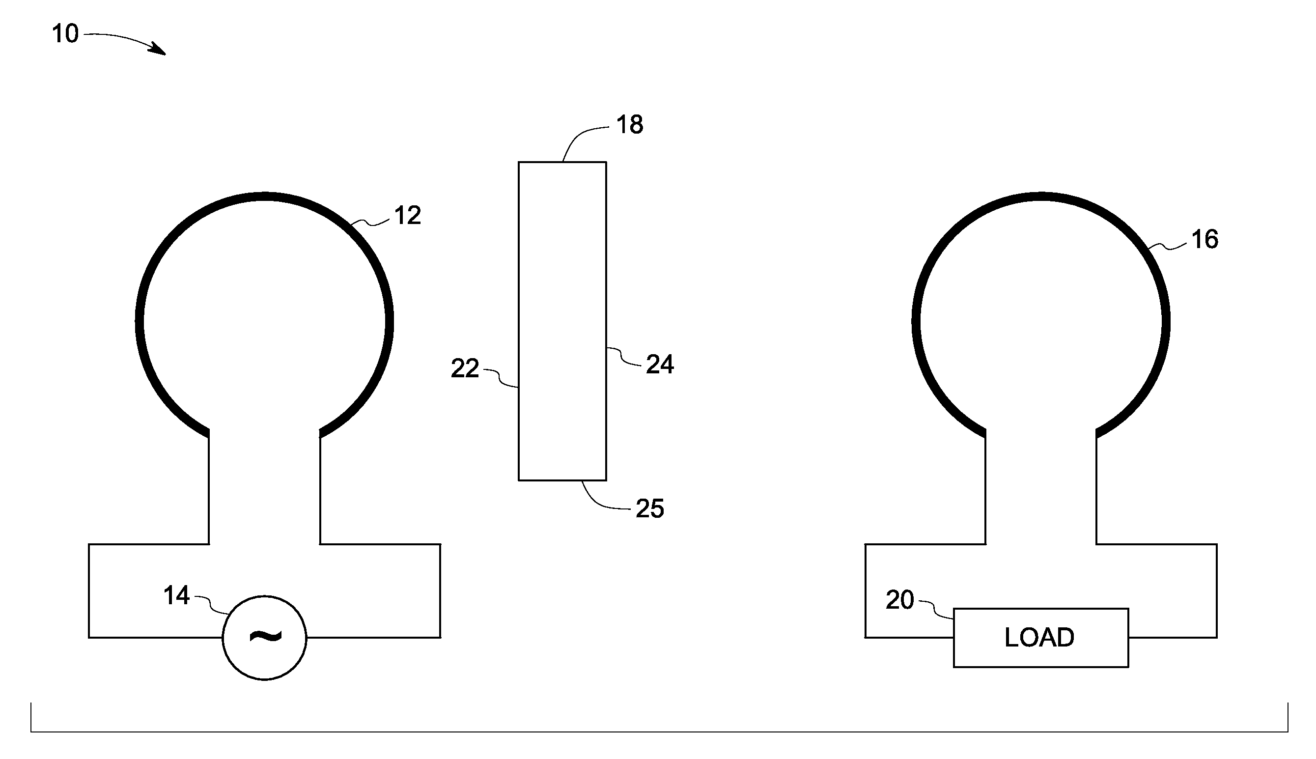
[0012]FIG. 1 illustrates an exemplary contactless power
transfer system according to an embodiment of the invention;
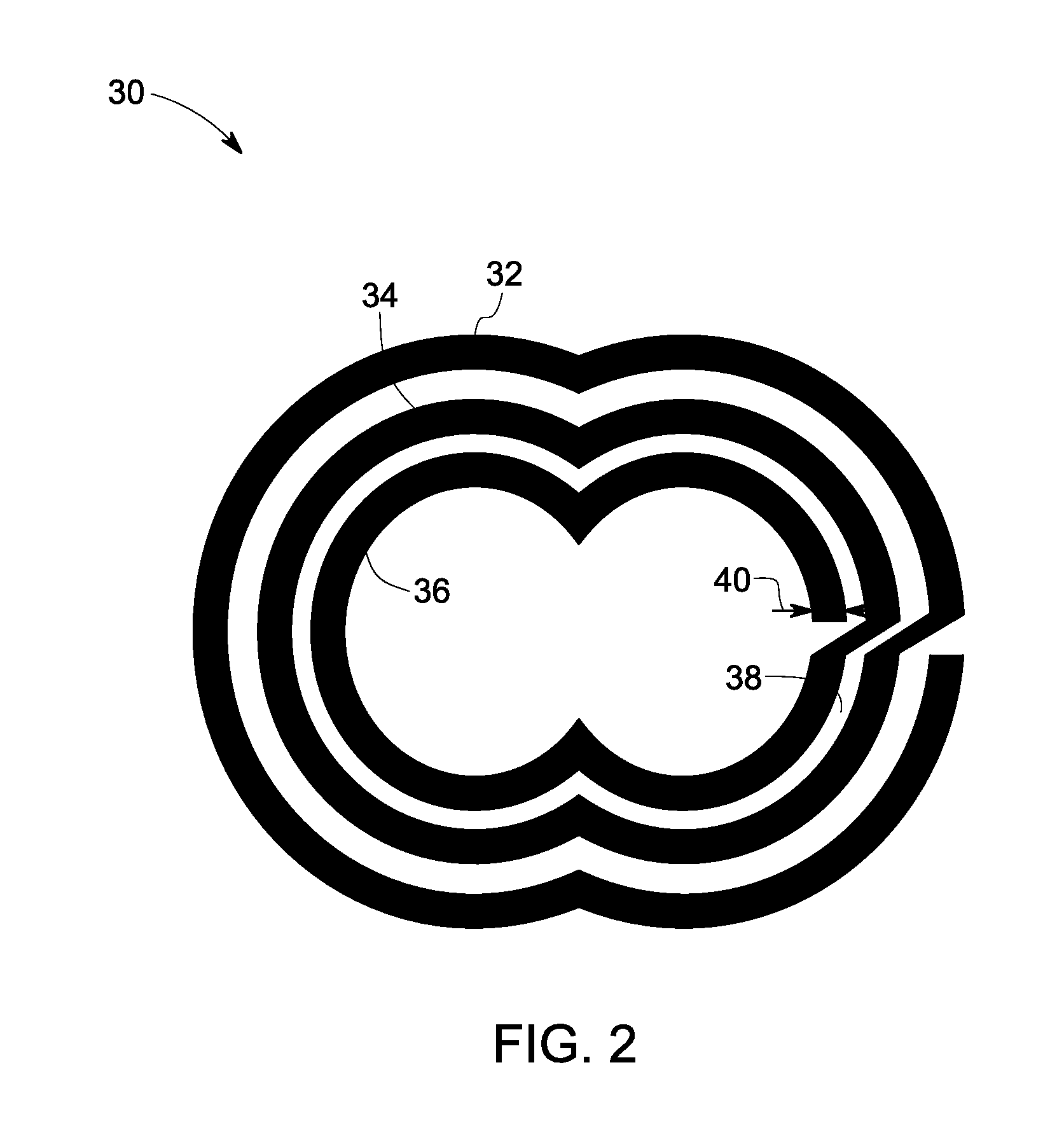
[0013]FIG. 2 illustrates an exemplary field-focusing element according to an embodiment of the invention;
[0014]FIG. 3 illustrates multiple exemplary structures of field-focusing elements according to various embodiments of the invention;
[0015]FIG. 4 illustrates an embodiment wherein a plurality of resonators are arranged in an array and implemented as a field-focusing element; and
[0016]FIG. 5 illustrates multiple exemplary structures of embedding materials according to an embodiment of the invention.
[0017]Embodiments of the present invention include power transfer systems and the
dielectric materials that can be used for power transfer systems.
[0018]In the following specification and the claims that follow, the singular forms “a”, “an” and “the” include plural referents unless the context clearly dictates otherwise.
[0019]Contactless power transfer systems are typically characterized by
short distance power transfer between primary and secondary coils. For example, one embodiment of an inductive power transfer
system uses a primary coil and a secondary coil to transfer power between two circuits in
galvanic isolation. A
magnetic field is established around the primary coil when coupled to a power source. The quantity of power transferred from the primary coil to the secondary coil is proportional to the level of primary magnetic field linking the secondary coil. Electrical transformers use high permeability magnetic cores to link the magnetic field between primary and secondary coils and thus achieve efficiencies on the order of at least about 98%. However, when such systems are configured for contactless power transfer, the air gap between the two coils reduces the
magnetic field coupling. Such reduced
coupling affects efficiency of contactless power transfer systems.
[0020]Certain embodiments disclosed herein provide a robust contactless power transfer
system with reduced sensitivity to load variations, efficient power transfer during misalignment of coils, and a field-focusing structure that enhances power
transfer efficiency.
[0021]FIG. 1 illustrates an example of a contactless power transfer
system 10 according to an embodiment of the invention including a first coil 12 coupled to a power source 14 and configured to produce a magnetic field (not shown). A second coil 16 is configured to receive power from the first coil 12. As used herein, the term “first coil” may also be referred to as a “primary coil,” and the term “second coil” may also be referred to as a “secondary coil.” The primary and secondary coils can be made up of any good electrical conducting materials such as, for example,
copper. Field-focusing element 18 is disposed between the first coil 12 and the second coil 16 for focusing the magnetic field from power source 14. In another embodiment, the field-focusing element may be used to focus electric fields and / or electro-magnetic fields. The terms “magnetic field-focusing element” and “field-focusing element” are used interchangeably. In one embodiment, magnetic field-focusing element 18 is configured as a self-resonant coil and has a
standing wave current distribution when excited via the first coil. In another embodiment, the magnetic field-focusing element includes multiple resonators operating as an
active array or a passive array and each
resonator configured as a self-resonant coil with a
standing wave current distribution. In yet another embodiment, the magnetic field-focusing element includes multiple sets of such resonators, each such
resonator set excited at a particular phase. It may be appreciated that, when exciting the sets of resonators via different phases, field-focusing may be enhanced in a desired direction.
[0022]
Magnetic field-focusing element 18 is further configured to focus the magnetic field onto the second coil 16 enhancing the
coupling between the first coil 12 and the second coil 16. In one embodiment, a non-uniform magnetic field distribution is developed around magnetic field-focusing element 18 by creating a
standing wave current distribution in the field-focusing element 18. In the illustrated embodiment, field-focusing element 18 is placed closer to the first coil 12 as an example. It may be advantageous in certain systems to place the field-focusing element 18 closer to the second coil 16. A load 20 is coupled to the second coil 16 to utilize the power transferred from the power source 14. In certain embodiments, the contactless power transfer system 10 may also be configured to simultaneously transfer power from the second coil to the first coil such that the system is capable of bidirectional power transfer. Non-limiting examples of potential loads include a
bulb, a battery, a computer, a sensor, or any device that requires electrical power for operation.
[0023]The contactless power transfer system 10 may be used to transfer power from the power source 14 to the load 20. In one embodiment, the power source 14 comprises a single-phase
AC power generator or three-phase
AC power generator in combination with power conversion
electronics to convert the
AC power to a higher frequency. When the first coil 12 is excited at the resonant frequency of magnetic field-focusing element 18, a standing wave current distribution is developed within the magnetic field-focusing element 18 between two open ends (22, 24) of the field-focusing element. The standing wave current distribution leads to a non-uniform magnetic field distribution around magnetic field-focusing element 18. Such non-uniform current distribution is configured to focus magnetic field in any desired direction, such as, in a direction of the second coil 16 in this example. When operating at resonant frequency, even a small excitation to magnetic field-focusing element 18 produces a large amplitude of current distribution along the length 25 of the magnetic field-focusing element. This large current magnitude of non-uniform distribution leads to an amplified and focused magnetic field in the direction of second coil 16 that results in higher efficiency of power transfer.
[0024]FIG. 2 illustrates an example of a field-focusing element according to an embodiment of the invention. Among the various structures that may be implemented as the magnetic field-focusing element 18 in FIG. 1, one such structure is illustrated in FIG. 2. In the illustrated embodiment, the reference numeral 30 is a field-focusing structure herein referenced as an “
Omega structure” and operates in a range of a few megahertz. The “
Omega structure” enables
high capacitance and
inductance and also enables negative permeability at near resonant frequency. Negative permeability helps with dominant field response and is effective in controlling the magnetic field. Resonant frequency of such structures can be controlled by varying the number of turns (32, 34, 36), the gap between the turns (38), and the width of the spiral (40). With an increased perimeter as compared to a spiral structure, the “
omega structure” requires reduced structural size to operate at lower
resonance frequency.
[0025]FIG. 3 illustrates multiple examples of structures for field-focusing elements according to various embodiments of the invention. In one embodiment, the field-focusing element includes a
single loop coil 50. In another embodiment, the field-focusing element includes multiple turns such as in a
split ring structure 52, spiral structure 54, Swiss-roll structure 56, or
helical coil 58. Selection of a structure for a particular application is determined by the size and self-resonating frequency of the field-focusing element. For example, in low power applications (less than about 1
Watt, for example), a
resonance frequency up to about 1000 MHz is feasible. In high power applications (from about one hundred Watts to about 500 kilowatts, for example), the resonance frequency of the order of several hundred kHz is feasible.
[0026]FIG. 4 illustrates an embodiment wherein a plurality of resonators are arranged in an array and implemented as a field-focusing element. An array of resonators constitutes multiple
resonator coils arranged in a particular array arrangement, such as a linear or
planar array, that is excited with a specific
phase relationship. Individual resonators (66-77) or sub-
wavelength resonators are configured to focus the magnetic field in a desired direction. In such an arrangement, fields from resonators in the array interfere constructively (add) in a desired direction to achieve magnetic field-focusing and interfere destructively (cancel each other) in the remaining space. In another embodiment, the resonators are arranged in at least one of a linear, a circular, a planar, or a three-dimensional array. In the illustrated embodiment, individual resonators 70-74 are arranged in a row and four such rows 66-69 are arranged one below the other. Individual resonators that are part of the array 64 are collectively configured for at least one or more resonant frequencies. In a particular embodiment, all of the individual resonators of the array are identical within the normal scope of variation expected for manufacturing and other common sources of variation.
[0027]In one embodiment of the power transfer system of the present invention, the resonator of the field-focusing element 18 can be made of dielectric materials in the form of, for example, dielectric cavity resonators. The dielectric materials used in field-focusing element desirably have high dielectric constant (
dielectric permittivity, ∈) and low loss tangent. The high dielectric constant helps in achieving the
low frequency of resonance with given smaller dimensions of resonator while the low loss tangent is desirable to keep the dielectric losses within acceptable limits.
[0028]In one embodiment, the field-focusing element 18 comprises a self-resonant coil that focuses the magnetic field upon excitation at the resonant frequency. The resonator is self-resonant coil of any shape whose self-resonant frequency depends upon the self-
capacitance and self-
inductance. The self-resonant frequency of the coil is dependant on the coil geometrical parameters. For example, in the case of
helical resonator coil, the resonance frequency is such that the overall length of the
helix is half
wavelength or multiples of half
wavelength of electromagnetic excitation. As a result, design of these resonators at low frequencies is challenging due to the space constraints. One of the methods to miniaturize the size of resonators is to embed the resonator in a high dielectric constant medium.
[0029]In one embodiment, a resonator or an array of resonators of the field-focusing element 18 is embedded in a material having high dielectric constant or a magnetic material having high permeability or
magneto-dielectric medium having
high dielectric permittivity and high magnetic permeability to achieve lower resonant frequency with a smaller sized resonator. High permeability material enhances self-
inductance of the resonator and high
permittivity material enhances self-
capacitance of the resonators to reduce the frequency of resonance. In another embodiment, high permeability materials are also configured to increase the
coupling between the primary coil and the field-focusing element, and between the field-focusing element and the secondary coil. The high dielectric constant of the embedding material helps in decreasing the operational frequency range of the resonators. The effect of dielectric constant in the
frequency reduction is presented in Table 1.
[0030]When the resonator is embedded in dielectric medium the inter-turn
capacitance between the turns of the coil increases which in turn helps to reduce the resonant frequency of the resonator. With high dielectric constant,
size reduction of the resonator is possible to a great extent. Another
advantage of high dielectric constant is the confinement of
electric field within the resonator, improving the efficiency of power transfer as the
radiation losses are diminished. But one of the critical design criteria of the selection of material with high dielectric constant is the loss tangent of that material at the
operating frequency. The low
dielectric loss tangent ensures the maximum
coupling efficiency. If the loss tangent is high, the loss in the form of heat will be high in the resonator. The issue of heat loss is of importance when the power levels are high. For low power levels, the high loss tangent values are acceptable. A high dielectric constant and extremely low loss tangent dielectric material is desirable in application where the power levels are more than one kW. The high dielectric constant helps to achieve miniaturized resonators at frequencies of hundreds of kHz and the low loss tangent helps to reduce the losses in the dielectric.


