Graphene-based saturable absorber devices and methods

a saturable absorber and graphene technology, applied in the direction of paper/cardboard containers, instruments, containers, etc., can solve the problems of complex and costly clean-room-based fabrication systems for sesams, low optical damage thresholds, and increased cavity loss and laser complexity, so as to improve the performance and facilitate the integration with the fabrication process. , the effect of reducing the cost of fabrication

Inactive Publication Date: 2012-02-16
NAT UNIV OF SINGAPORE +1
View PDF3 Cites 61 Cited by
  • Summary
  • Abstract
  • Description
  • Claims
  • Application Information

AI Technical Summary

Benefits of technology

[0010]The present invention overcomes the problems described above, namely better performance, cheaper fabrication and easier integration with the fabrication process compared to conventional methods involving SESAMS or SWCNTs.
[0011]Graphene is a material that is mechanically and chemically robust, exhibiting high conductivity and advantageous optical properties, such as interband optical transition and universal optical conductance. In terms of its use as saturable absorber, graphene materials also have lower non-saturable loss, higher conversion efficiency and wideb

Problems solved by technology

However, there are a number of drawbacks associated with SESAMs.
SESAMs require complex and costly clean-room-based fabrication systems, such for Metal-Organic Chemical Vapor Deposition (MOCVD) or Molecular Beam Epitaxy (MBE).
Other laser cavity topologies, such as the ring-cavity cavity design, which requires a transmission-mode device, which offers advantages such as doubling the repetition rate for a given cavity length, and which is less sensitive to reflection-induced instability with the use of optical isolators, is not possible unless an optical circulator is employed, which increases cavity loss and laser complexity.
SESAMs also suffer

Method used


Image

  • Graphene-based saturable absorber devices and methods
  • Graphene-based saturable absorber devices and methods
  • Graphene-based saturable absorber devices and methods

Examples


example 1

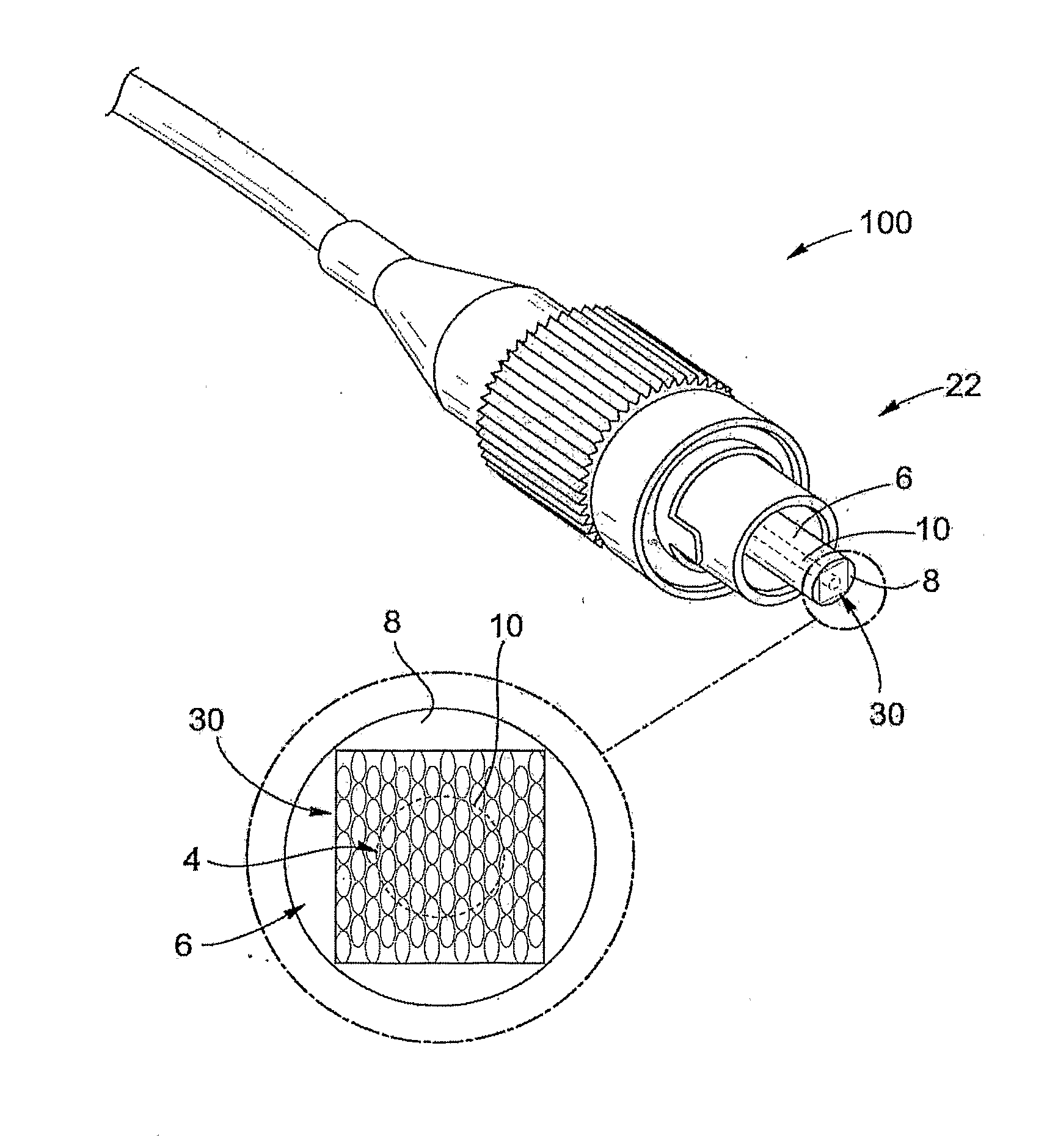
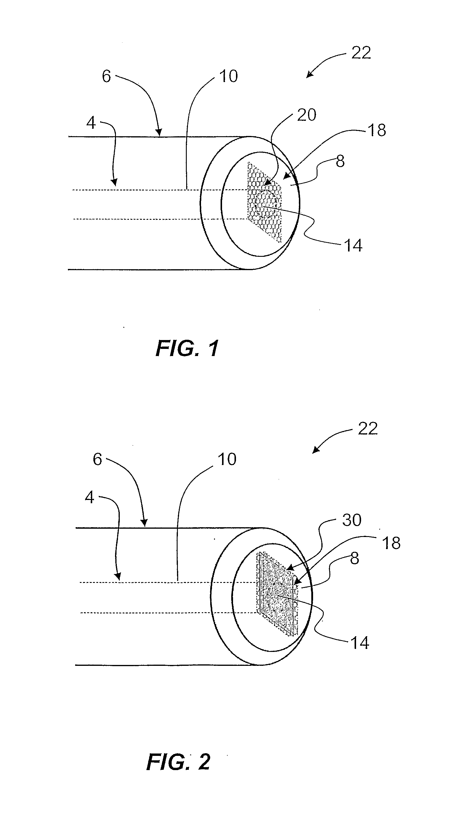
[0034]FIG. 1 is perspective view of an optical fiber 10 having an end facet 14 that has assembled thereon a graphene-based saturable absorber material 18 in the form of a monolayer graphene film 20 (i.e., one atomic layer of graphene, or “graphene monolayer”) to function as a saturable absorber device 22. The saturable absorber device 22 of FIG. 1 is suitable for use in mode locking and Q-switching fiber lasers, as described below. FIG. 1 shows optical fiber 10 held within an axial pinhole 4 of a ferrule 6 that has an endface 8. Ferrule 6 serves as a fiber holder.

[0035]A graphene monolayer 20 can be obtained using methods such as, for example, mechanically exfoliation, epitaxial growth, chemical vapor deposition and chemical processed (solution processed) methods, as well as laser ablation and filtered cathodic arc methods. After graphene monolayer 20 has been properly prepared on a substrate, the monolayer is removed as a graphene film and is transferred onto the end facet 14 of op...

example 2

[0040]FIG. 2 is similar to FIG. 1 and is perspective view of optical fiber 10 with a graphene-based saturable absorber material 18 in the form of multilayer graphene film 30 (i.e., multiple atomic layers of graphene, or a “graphene multilayer”) assembled on fiber end facet 14 to function as a saturable absorber device 22. The saturable absorber device 22 of FIG. 2 is suitable for use in mode locking and Q-switching fiber lasers, as described below.

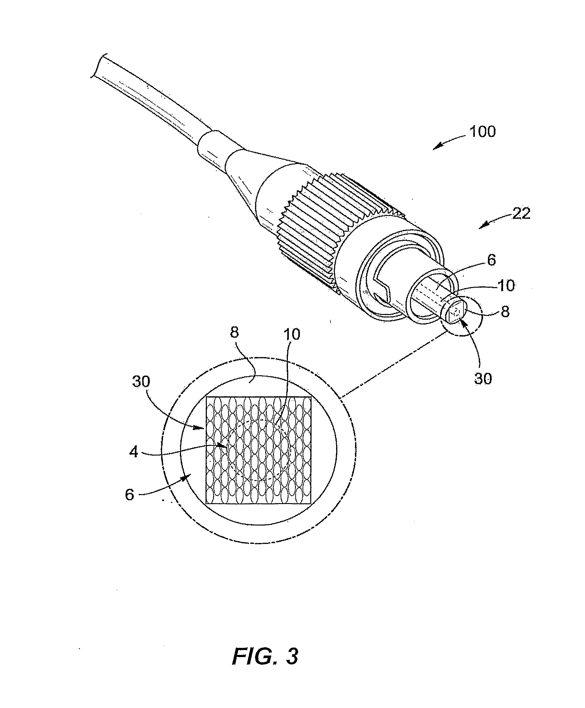
[0041]FIG. 3 is a photograph of a fiber pigtail 100 with ferrule 6 that holds optical fiber 10, with multilayer graphene film 30 on endface 8 covering pinhole 4 and fiber end facet 14. Fiber pigtail 100 is inserted into a fiber laser to generate mode locking or Q-switching pulses, as described below.

[0042]FIG. 4 is an enlarged optical image of the end face of fiber pigtail 100 showing a graphene-based saturable absorber material 18 in the form of multilayer graphene 30 on ferrule endface 8 covering pinhole 4 and fiber end facet 14. The as-...

example 3

[0047]FIG. 5 is perspective view of optical fiber 10 similar to FIG. 1 and having a graphene-based saturable absorber material 18 in the form of graphene film 40. Graphene film 40 is formed form monolayer graphene flakes 42 assembled on fiber end facet 14, thereby forming saturable absorber device 22. The saturable absorber device 22 of FIG. 5 is suitable for use in mode locking and Q-switching fiber lasers, as described below.

[0048]In an example, monolayer graphene flakes 42 have a small size, e.g., less than 10 μm. In an example, graphene flakes 42 are assembled onto the end facet of fiber pigtail as a graphene film 40 that covers the pinhole 4, and the pigtail 100 is inserted into a fiber laser to generate mode locking or Q-switching pulses. The small size of graphene flakes 42 are obtained in one example by solution processing routes or by post-treatment of monolayer graphene on a substrate. The post-treatment method includes, but are not limited to, etching chemically (e.g., ac...


PUM

PropertyMeasurementUnit
Photochromicaaaaaaaaaa

Abstract

A graphene-based saturable absorber device suitable for use in a ring-cavity fiber laser or a linear-cavity fiber laser is disclosed. The saturable absorber device includes an optical element and a graphene-based saturable absorber material supported by the optical element and comprising at least one of graphene, a graphene derivative and functionalized graphene. An examplary optical element is an optical fiber having an end facet that supports the saturable absorber material. Various forms of the graphene-based saturable absorber materials and methods of forming same are also disclosed.

Description

CLAIM OF PRIORITY[0001]This Application claims priority from U.S. Provisional Patent Application Ser. No. 61 / 168,661, entitled “Optical element,” filed on Apr. 13, 2009.FIELD[0002]The present invention relates to saturable absorbers for fiber lasers, and in particular relates to graphene-based saturable absorber devices and methods for use in fiber lasers for mode-locking, Q-switching, optical signal processing and the like.BACKGROUND ART[0003]Fiber mode-locked lasers have replaced bulk solid state lasers in many research / industrial fields that need high-quality optical pulses. The advantages include simplicity of structure, outstanding pulse quality and efficient operation. The development of compact, diode-pumped, ultrafast fiber lasers as alternatives for bulk solid-state lasers is making rapid progress recently.[0004]At present, short pulse generation has been particularly effective using passive mode-locking techniques. The dominant technology in passively mode-locked fiber las...

Claims


Application Information

Patent Timeline
IPC IPC(8): H01S3/30B05D5/06B32B37/02B32B37/12B29C35/08C30B23/02C30B25/02H01S3/08B32B37/14B82Y20/00B82Y40/00
CPCH01S3/1118H01S3/06708H01S3/06725H01S3/06791H01S3/094046H01S3/10076H01S3/113H01S3/1608H01S2301/085Y10T156/10G02F1/3523H01S3/067H01S3/094003
Inventor KIAN, LOH PINGBAO, OIAOLIANGTANG, DING YUANZHANG, HAN
Owner NAT UNIV OF SINGAPORE
Why Eureka
Try Eureka