
Method of forming pattern using actinic-ray or radiation-sensitive resin composition, and pattern

a technology of resin composition and forming pattern, which is applied in the direction of photomechanical treatment originals, instruments, photomechanical equipment, etc., can solve the problems of reducing optical contrast, difficult to find an appropriate combination, and inability to obtain satisfactory exposure margin and focal depth

Active Publication Date: 2012-03-29
FUJIFILM CORP
View PDF2 Cites 23 Cited by
  • Summary
  • Abstract
  • Description
  • Claims
  • Application Information

AI Technical Summary

Benefits of technology

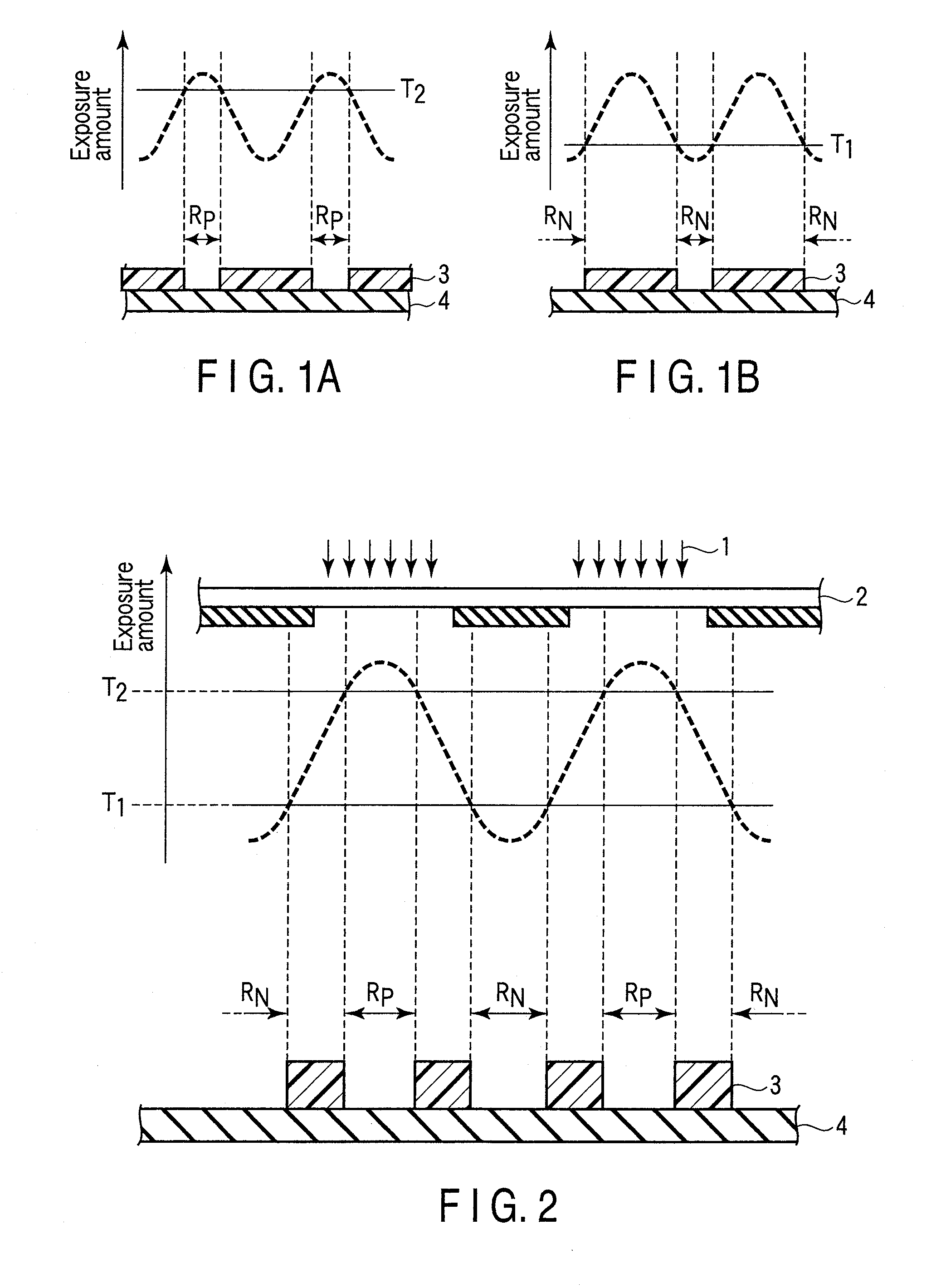
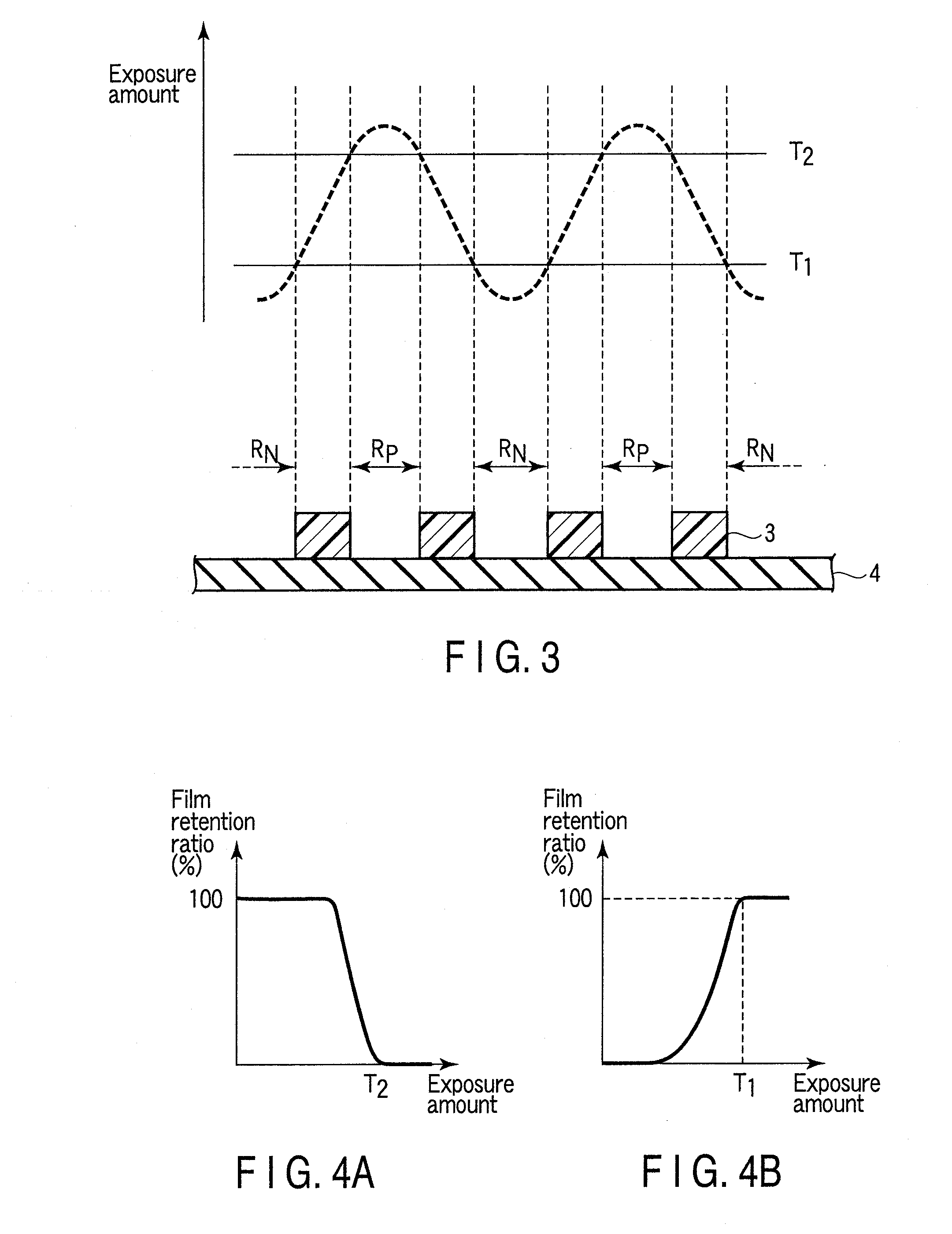
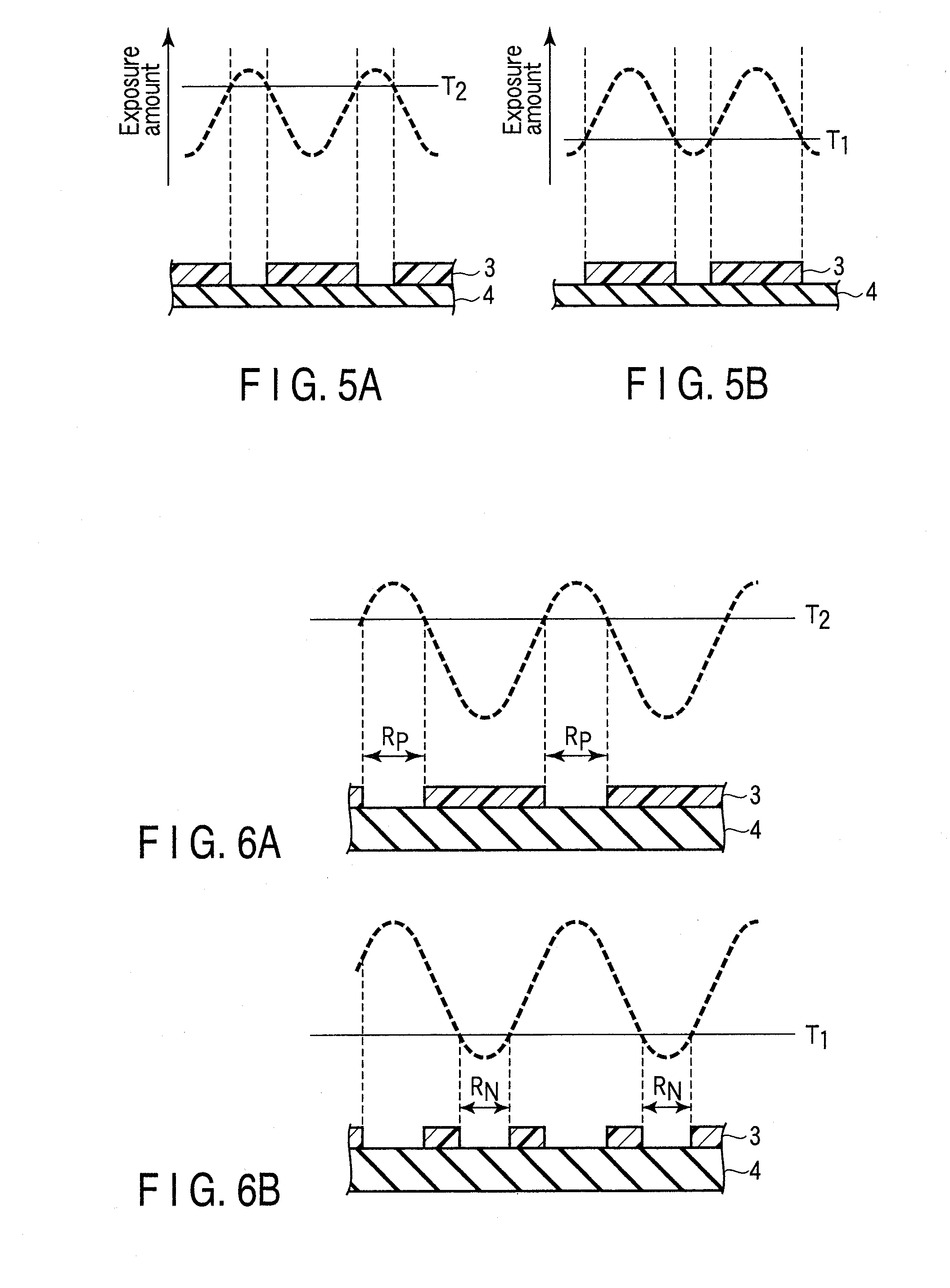
[0026]It is an object of the present invention to provide a method of forming a pattern using an actinic-ray- or radiation-sensitive resin composition that excels in line width roughness (LWR), focus latitude (depth of focus, DOF) and pattern configuration in order to more stably produce a micropattern of high precision required for manufacturing electronic devices of high integration and high precision. It is another object of the present invention to provide a pattern formed by the above method.
[0036]The present invention has made it feasible to provide a pattern excelling in line width roughness (LWR), focus latitude (depth of focus, DOF) and pattern configuration in a patterning involving negative development or a patterning in which both negative development and positive development are carried out.

Problems solved by technology

However, in accordance with the miniaturization of the pattern size, the conventional exposure system poses the problem that light beams having been irradiated to adjacent patterns interfere with each other, which reduces the optical contrast.
However, the patterning by simple application of the conventional resist composition to the conventional resist processing poses the problem that as patterning must be performed in the vicinity of the resolution limit of the resist in this double exposure system, satisfactory exposure margin and focal depth cannot be obtained.
However, the current situation is that it is extremely difficult to find an appropriate combination of resist composition, developer, rinse liquid, etc. as required for forming a pattern of comprehensively excellent performance, so that an improvement has been demanded in this field.
However, it is extremely difficult to select the most appropriate combination of resist composition and negative developer.
The above-mentioned technique encounters the problem that the developability upon the use of the negative developer is deteriorated.
Further, in the formation of a micropattern by double development, it is unsatisfactory to only ensure a high resolving power upon the independent use of either a negative developer or a positive developer.

Method used


Image

  • Method of forming pattern using actinic-ray or radiation-sensitive resin composition, and pattern
  • Method of forming pattern using actinic-ray or radiation-sensitive resin composition, and pattern
  • Method of forming pattern using actinic-ray or radiation-sensitive resin composition, and pattern

Examples


synthetic example 1

Synthesis of Resin (P-1)

[0456]In a nitrogen stream, 40 g of a solvent consisting of a 6 / 4 (mass ratio) mixture of propylene glycol monomethyl ether acetate and propylene glycol monomethyl ether was placed in a three-necked flask and heated at 80° C. (solvent 1). The monomers corresponding to the following repeating units mixed in a molar ratio of 20 / 20 / 10 / 20 / 30 were dissolved in a solvent consisting of a 6 / 4 (mass ratio) mixture of propylene glycol monomethyl ether acetate and propylene glycol monomethyl ether, thereby obtaining a 22 mass % monomer solution (400 g). Polymerization initiator V-601 (produced by Wako Pure Chemical Industries, Ltd.) was added thereto in an amount of 8 mol % based on the monomers and dissolved. The thus obtained solution was dropped into the solution 1 over a period of 6 hours. After the completion of the dropping, reaction was continued at 80° C. for 2 hours. The reaction liquid was allowed to stand still to cool and was dropped into a mixture consistin...

synthetic example 2

Synthesis of Triphenylsulfonium Acetate

[0459]In a flask, 5.07 g (13 mmol) of triphenylsulfonium iodide, 2.25 g (13.5 mmol) of silver acetate, 120 ml of acetonitrile and 60 ml of water were mixed together and agitated at room temperature for one hour. The reaction solution was filtered, thereby obtaining a solution of triphenylsulfonium acetate.

synthetic example 3

Synthesis of Compound PAG-1

[0460]In a nitrogen stream, 28.0 g (88.55 mmol) of 1,1,2,2,3,3-hexafluoropropane-1,3-disulfonyl difluoride, 17.92 g (177.1 mmol) of triethylamine and 210 ml of diisopropyl ether were cooled with ice. A solution consisting of a mixture of 7.56 g (88.2 mmol) of piperidine and 105 ml of diisopropyl ether was dropped thereinto over a period of 30 minutes. The mixture was agitated while cooling with ice for one hour and further agitated at room temperature for one hour. The resultant organic phase was sequentially washed with water, a saturated aqueous ammonium chloride solution and water, and dried over sodium sulfate. The solvent was evaporated off, and 140 ml of ethanol and 1400 mg of sodium hydroxide were added to the dried matter and agitated at room temperature for two hours. Dilute hydrochloric acid was added so as to neutralize the reaction solution, thereby obtaining an ethanol solution of sulfonic acid.

[0461]The solution of triphenylsulfonium acetate ...


PUM

PropertyMeasurementUnit
Percent by massaaaaaaaaaa
Temperatureaaaaaaaaaa

Abstract

According to one embodiment, a method of forming a pattern includes the step of applying an actinic-ray- or radiation-sensitive resin composition on a substrate so as to form a film, the step of selectively exposing the film through a mask and the step of developing the exposed film with the use of a developer containing an organic solvent, wherein the actinic-ray- or radiation-sensitive resin composition contains a resin (A) whose polarity is increased by the action of an acid so that the solubility of the resin in the developer containing an organic solvent is decreased, a photoacid generator (B) that when exposed to actinic rays or radiation, generates an acid containing a fluorine atom and a solvent (C), and wherein the photoacid generator (B) is contained in the composition in a ratio of 8 to 20 mass % based on the total solids of the composition.

Description

CROSS-REFERENCE TO RELATED APPLICATIONS[0001]This application is based upon and claims the benefit of priority from prior Japanese Patent Applications No. 2009-135251, filed Jun. 4, 2009; and No. 2009-257972, filed Nov. 11, 2009, the entire contents of both of which are incorporated herein by reference.TECHNICAL FIELD[0002]The present invention relates to a method of forming a pattern using an actinic-ray- or radiation-sensitive resin composition for use in a semiconductor production process for an IC or the like, a circuit board production process for a liquid crystal, a thermal head or the like and other photofabrication lithography processes, and also relates to a pattern formed by the method. More particularly, the present invention relates to a method of forming a pattern with the use of an actinic-ray- or radiation-sensitive resin composition that is suitable for exposure by means of an ArF exposure unit or liquid-immersion projection exposure unit using far ultraviolet of a w...

Claims


Application Information

Patent Timeline
IPC IPC(8): G03F7/20
CPCC08F20/28G03F7/0045G03F7/325G03F7/0397G03F7/095G03F7/0046
Inventor ENOMOTO, YUICHIROTARUTANI, SHINJISHIBUYA, AKINORIYAMAGUCHI, SHUHEI
Owner FUJIFILM CORP
Learn More