
Carbonaceous Nanocomposite Having Novel Structure And Fabrication Method Thereof

a carbonaceous nanocomposite and novel structure technology, applied in the direction of vacuum evaporation coating, transportation and packaging, coating, etc., can solve the problems of inconvenient mass production, difficult control of the thickness and length of carbon nanotubes, and inconvenient mass production methods, etc., to achieve excellent adhesion to the substrate, reduce the electrical resistance of graphene and carbon nanotubes, and high current density

Active Publication Date: 2012-08-02
INJE UNIV IND ACADEMIC COOP FOUND
View PDF5 Cites 53 Cited by
  • Summary
  • Abstract
  • Description
  • Claims
  • Application Information

AI Technical Summary

Benefits of technology

[0021]The carbonaceous nanocomposite according to the present disclosure has excellent adhesivity to the substrate and can be attached to the substrate without undergoing a pasting process. Since a two-directional current flow is generated, the electrical resistance of the graphene and carbon nanotube is considerably reduced. In addition, the graphene allows the carbon nanotube to have a high current density and a high specific surface area, thereby accelerating a redox reaction. The excellent heat-radiating property of the graphene sheet allows fast transfer of heat generated in the carbon nanotube to outside, thereby avoiding degradation of the carbon nanotube. Thus, when employed as an electrode for a battery or a field emission display, a higher current density and an extended lifespan can be achieved when compared with the existing art.

Problems solved by technology

However, this method is not suitable for mass production and large amounts of impurities such as amorphous carbon or metal powder are formed.
Thus, an additional purification process is necessary and the control of thickness and length of the carbon nanotube is not easy.
Like the arc discharge method, this method is not suitable for mass production because the yield is extremely low.
Although being advantageous for mass production, the method requires use of a catalyst and a high-temperature heat of 600-1000° C. Thus, a lot of efforts are required to remove the catalyst and glass or plastic substrates are inapplicable to the high-temperature process.
As a consequence, operation time is short and degradation occurs easily.
However, the thin film resulting from the attachment process has very poor electrical conductivity and other electrical properties as compared to direct growth owing to residual carbon resulting from the insulating binder material.
When carbon nanotube is used, electrical properties are degraded rapidly because of random horizontal arrangement during the preparation of the slurry in addition to the binder problem.
Due to these disadvantages, desired efficiency, brightness, or the like expected from the theoretical calculation cannot be achieved.
In addition, the carbonaceous nanomaterial is problematic in that device lifespan is reduced because of the heat generated during operation of the device.

Method used


Image

  • Carbonaceous Nanocomposite Having Novel Structure And Fabrication Method Thereof
  • Carbonaceous Nanocomposite Having Novel Structure And Fabrication Method Thereof
  • Carbonaceous Nanocomposite Having Novel Structure And Fabrication Method Thereof

Examples


example 1

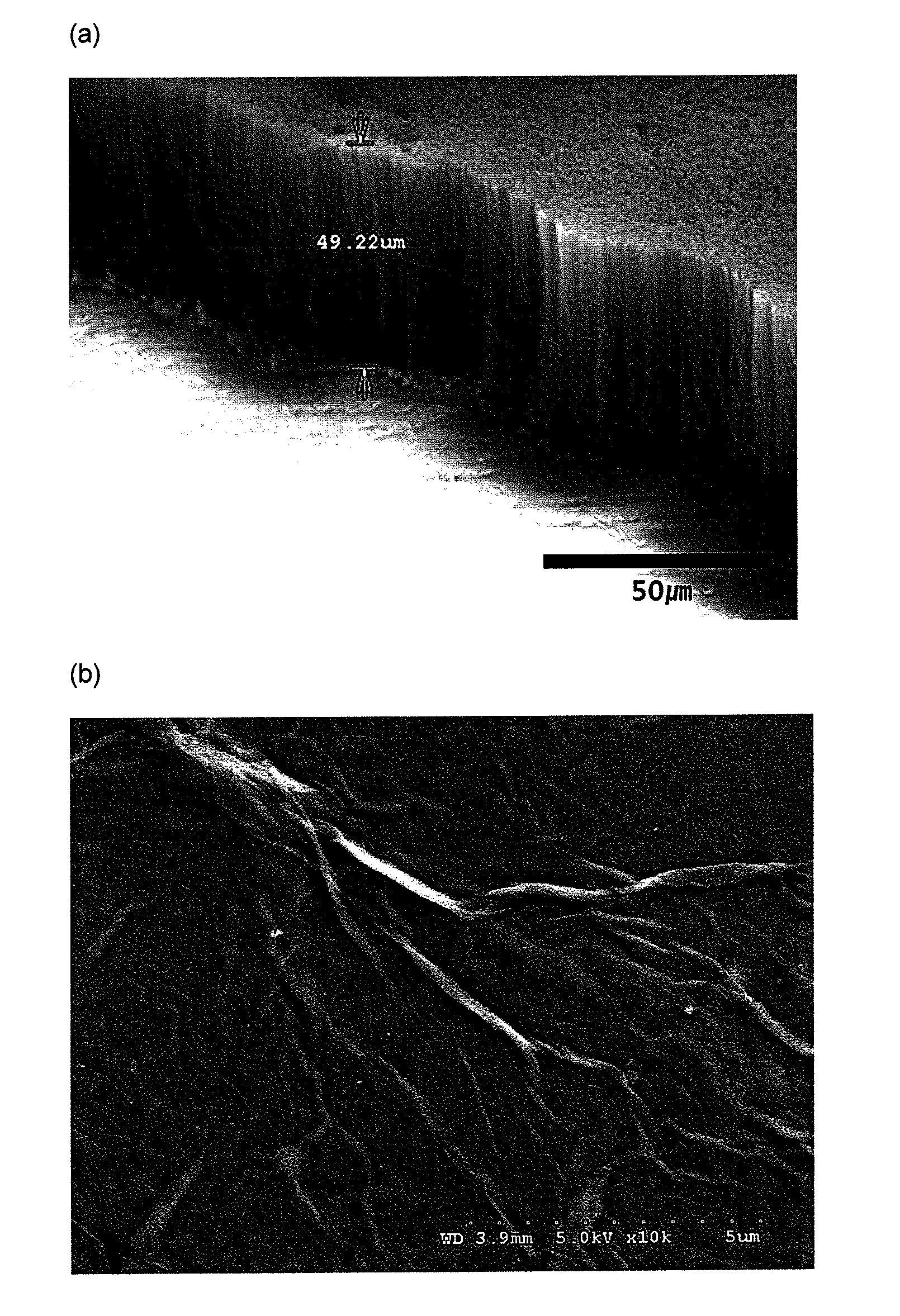
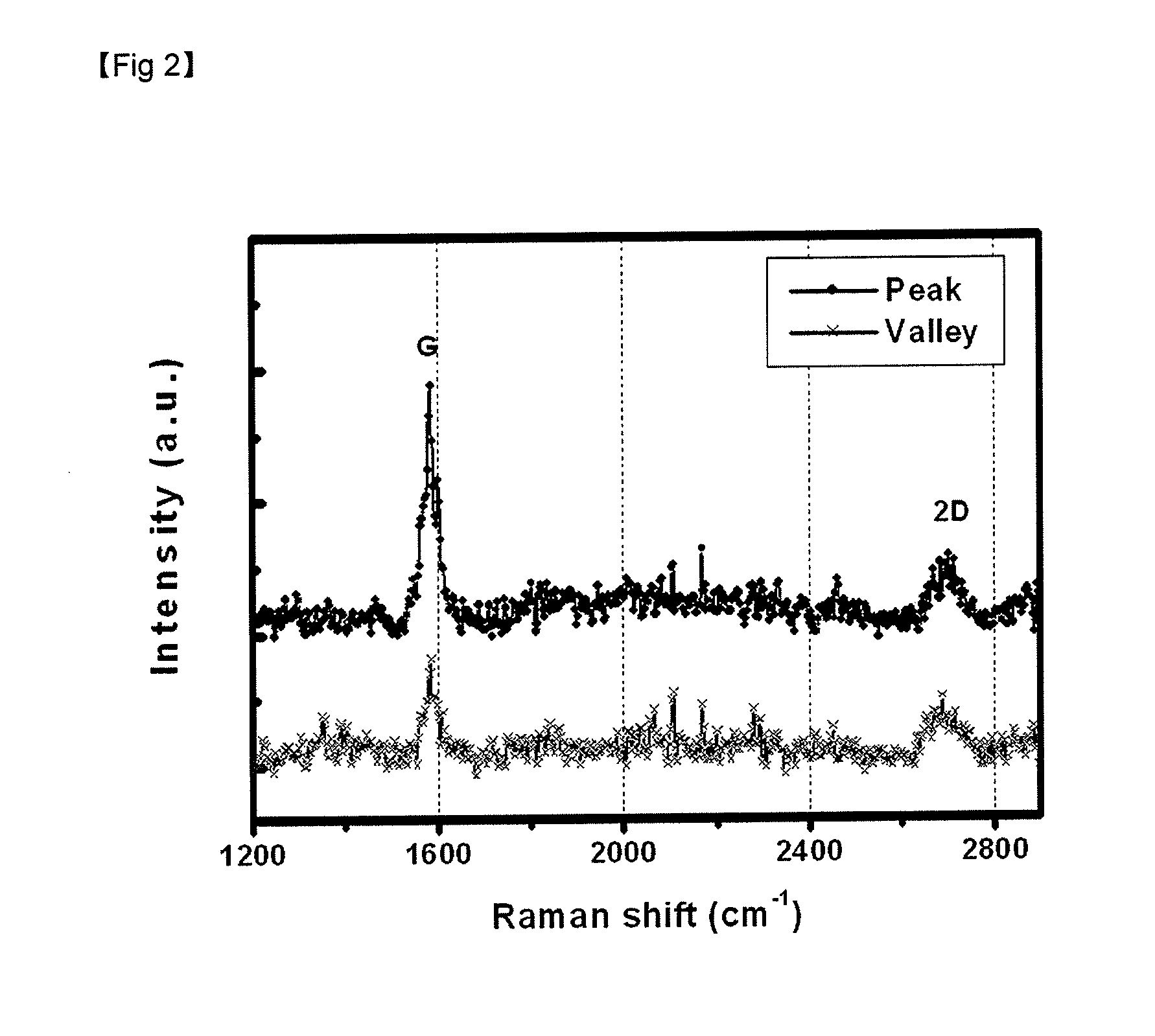
[0063]A silicon wafer was organically washed and an Fe catalyst was deposited to a thickness of 100 nm by RF ion sputtering. Then, the wafer was heated at 900° C. for 30 minutes at a pressure of 60 torr while flowing Ar gas at 500 sccm. After keeping at 900° C. for 5 minutes, carbon nanotube was grown for 10 minutes while flowing methane gas at 25 sccm. Then, several layers of graphene were grown on the silicon wafer by cooling for 50 minutes while flowing hydrogen gas at 500 sccm.

example 2

[0064]A vial was placed on a hot plate and, after adding H2SO4 (6 mL), heated to 80° C. After weighing and slowly adding K2S2O8 and P2O5 (2 g), graphite powder (4 g) was added. When deep blue color was developed, the reaction mixture was cooled at room temperature (25° C.) for 6 hours. Then, the graphite powder was filtered using filter paper. The filtered graphite powder was washed with deionized water until pH 7.

[0065]After filtration and washing, the graphite powder was dried overnight at room temperature (25° C.) to obtain graphite oxide (GO). An ice box containing a Teflon beaker, ice and salt was placed on a mechanical stirrer. Then, saturated H2SO4 (92 mL) and the graphite oxide were added to the Teflon beaker.

[0066]KMnO4 (12 g) was slowly added while keeping the temperature inside the Teflon beaker at 20° C. or lower. When the reaction became stable after the addition of KMnO4, the mixture was stirred at 35° C. for 2 hours. Then, deionized water (185 mL) was slowly added. 15...

example 3

[0067]Experiment was carried out in the same manner as in Example 2, except for dip coating a substrate in a graphite oxide solution, heating in a furnace at 300° C. for 5 hours and reducing oxygen by annealing to prepare graphene, in order to remove oxide groups from graphite oxide.


PUM

PropertyMeasurementUnit
Thicknessaaaaaaaaaa
Angleaaaaaaaaaa
Diameteraaaaaaaaaa

Abstract

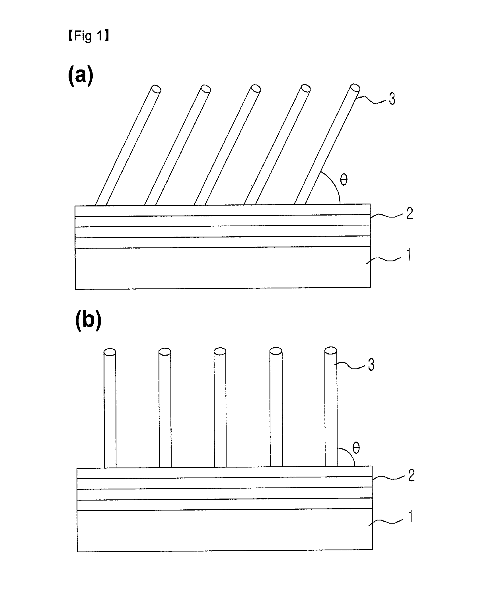
Disclosed is a carbonaceous nanocomposite including: a substrate; a graphene sheet formed on a top surface of the substrate in parallel with the substrate; and a carbonaceous nanomaterial provided on another surface of the graphene sheet, the nanomaterial having an aspect ratio of 2 to 75,000 to make a predetermined angle with the graphene sheet. The carbonaceous nanocomposite according to the present disclosure has excellent adhesivity to the substrate and can be attached to the substrate without undergoing a pasting process. Since a two-directional current flow is generated, the electrical resistance of the graphene and carbon nanotube is considerably reduced. In addition, the graphene allows the carbon nanotube to have a high current density and a high specific surface area, thereby accelerating a redox reaction. The excellent heat-radiating property of the graphene sheet allows fast transfer of heat generated in the carbon nanotube to outside, thereby avoiding degradation of the carbon nanotube. Thus, when employed as an electrode for a battery or a field emission display, a higher current density and an extended lifespan can be achieved when compared with the existing art.

Description

TECHNICAL FIELD[0001]The present disclosure relates to a carbonaceous nanocomposite having a novel structure, a method for fabricating the same, and an electrode for a battery and a field emission display using the carbonaceous nanocomposite. More particularly, the present disclosure relates to a carbonaceous nanocomposite having a novel structure capable of providing good adhesion to a substrate and extending device lifespan by reducing electrical resistance, a method for fabricating the same, and an electrode for a battery and a field emission display using the carbonaceous nanocomposite.BACKGROUND ART[0002]In general, carbon nanotube is widely used in various fields where carbonaceous nanomaterials are used. Carbon nanotube is an extremely fine cylindrical material with a very small diameter of several nanometers (nm). In the carbon nanotube, each carbon atom is bonded to three others carbon atoms, forming a hexagonal honeycomb structure. The carbon nanotube can be conducting or ...

Claims


Application Information

Patent Timeline
IPC IPC(8): H01L31/0224B05D1/36C23C14/34B05D3/02B05D3/10B32B5/02B05D1/38B82Y30/00B82Y40/00
CPCB82Y30/00B82Y40/00Y10T428/24C01B31/0438C01B31/022C01B32/158C01B32/182C01B32/159
Inventor JEON, MIN-HYONCHOI, HYON-KWANGHWANG, SOOK-HYUNKIM, HYUN-KOOK
Owner INJE UNIV IND ACADEMIC COOP FOUND
Learn More