
Optical devices for modulating light of photorefractive compositions with thermal control

a technology of photorefractive compositions and optical devices, applied in the field of optical devices, can solve problems such as data loss and data disorder, and achieve the effect of good diffraction efficiency

Inactive Publication Date: 2012-11-01
NITTO DENKO CORP
View PDF2 Cites 4 Cited by
  • Summary
  • Abstract
  • Description
  • Claims
  • Application Information

AI Technical Summary

Benefits of technology

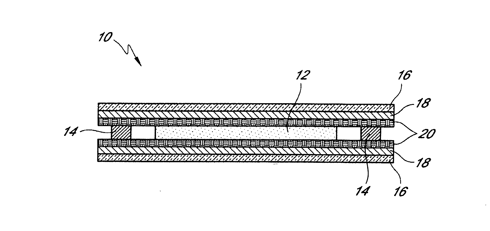
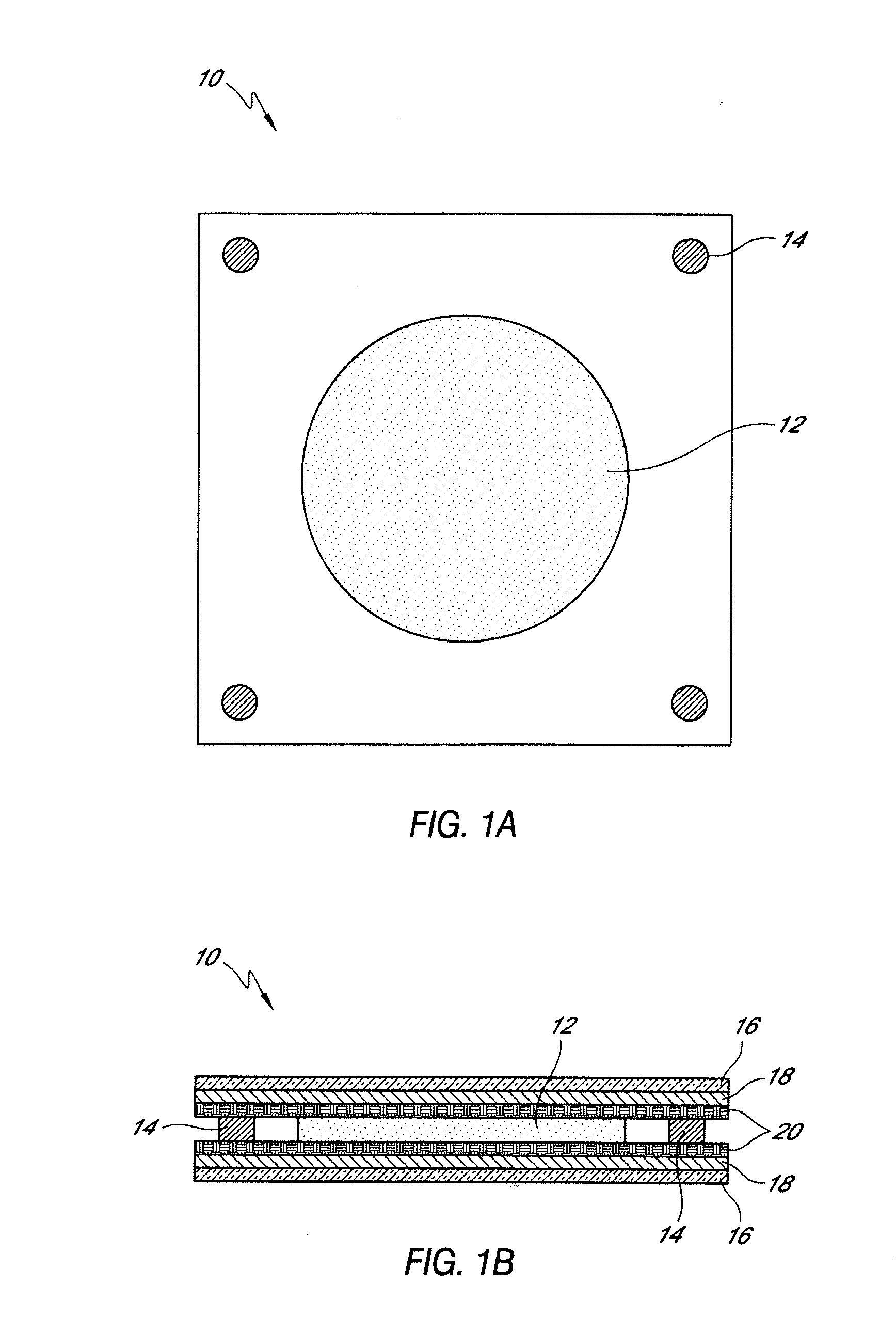
[0012]An embodiment of the present invention provides an optical device, wherein grating signals can be written and read without the use of a large external bias voltage. The grating can be held for long periods of times, ranging from hours to days, for holographic applications. Also, the grating signal can be controlled by thermal treatment. Embodiments of the organic based materials and holographic medium described herein show good diffraction efficiencies in response to lasers having a wavelength in the range of about 500 nm to about 700 nm. The availability of such materials that are sensitive to a continuous wave laser system can be greatly advantageous and useful for industrial applications, including sensor and optical filter applications.
[0015]Unlike conventional photorefractive compositions, which respond to laser irradiation upon the application of large external bias voltage, gratings can be written and read out of the preferred compositions described herein using little or no external bias voltage. Furthermore, the grating behavior of preferred compositions can be controlled using thermal treatment. Controlling the grating behavior can comprise enhancing or increasing the strength of the grating signal. Controlling the grating signal can also comprise turning the grating signal on and off. Preferred photorefractive compositions also exhibit good phase stability.

Problems solved by technology

For a variety of holographic applications, such as data storage, using a large amount of voltage to read data creates the risk of losing data or otherwise causing disorder to the data.

Method used


Image

  • Optical devices for modulating light of photorefractive compositions with thermal control
  • Optical devices for modulating light of photorefractive compositions with thermal control
  • Optical devices for modulating light of photorefractive compositions with thermal control

Examples


example 1

(a) Monomers Containing Charge Transport Groups

[0097]TPD acrylate type charge transport monomers (N-[acroyloxypropylphenyl]-N,N′,N′-triphenyl-(1,1′-biphenyl)-4,4′-diamine) (TPD acrylate) were purchased from Fuji Chemical, Japan. The TPD acrylate type monomer possessed the structure:

(b) Monomers Containing Non-Linear Optical Groups

[0098]The non-linear-optical precursor monomer 5-[N-ethyl-N-4-formylphenyl]amino-pentyl acrylate was synthesized according to the following synthesis scheme:

[0099]STEP I: Bromopentyl acetate (5 mL, 30 mmol), toluene (25 mL), triethylamine (4.2 mL, 30 mmol), and N-ethylaniline (4 mL, 30 mmol) were added together at room temperature. The mixture was heated at 120° C. overnight. After cooling down, the reaction mixture was rotary-evaporated to form a residue. The residue was purified by silica gel chromatography (developing solvent: hexane / acetone=9 / 1). An oily amine compound was obtained. (Yield: 6.0 g (80%))

[0100]STEP II: Anhydrous DMF (6 mL, 77.5 mmol) was ...

example 2

Preparation of Copolymer by AIBN Radical Initiated Polymerization (TPD Acrylate / Chromophore Type 10:1)

[0106]The charge transport monomer N-[(meth)acroyloxypropylphenyl]-N,N′,N′-triphenyl-(1,1′-biphenyl)-4,4′-diamine (TPD acrylate) (43.34 g), and the non-linear optical precursor monomer 5-[N-ethyl-N-4-formylphenyl]amino-pentyl acrylate (4.35 g), prepared as described in Example 1, were put into a three-necked flask. After toluene (400 mL) was added and purged by argon gas for 1 hour, azoisobutylnitrile (118 mg) was added into the solution. Then, the solution was heated to 65° C., while continuing to purge with argon gas.

[0107]After 18 hrs of polymerization, the polymer solution was diluted with toluene. The polymer was precipitated from the solution and added to methanol, then the resulting polymer precipitate was collected and washed in diethyl ether and methanol. The white polymer powder was collected and dried. The yield of polymer was 66%.

[0108]The weight average and number avera...

example 3

Fabrication of Inert Layer Modified ITO Glass

[0109]About 2.0 g of polymer (amorphous polycarbonate) powder was dissolved in about 20 ml dichloromethane. The solution was stirred under ambient condition overnight to ensure substantially total dissolution. The solution was then filtered through an approximately 0.2 μm PTFE filter and spin-coated onto ITO glass substrate. The film was then pre-baked at about 80° C. for about a minute, and vacuum baked at about 80° C. overnight. The thickness of the inert layer was adjustable to be between about 0.5 μm and about 50 μm, depending on the initial spin-coating speed and polymer concentration.

Production of Optical Device

[0110]A photorefractive composition testing sample was prepared. The components of the composition were provided in approximate amounts as follows:

(i) Matrix polymer (described in Example 2):46.93 wt %(ii) NPP chromophore25.03 wt %(iii) Ethylhexyl carbazole plasticizer25.03 wt %(iv) Anthraquinone sensitizer 3.01 wt %

[0111]To ...


PUM


Abstract

Described herein are optical devices comprising a photorefractive layer and at least two inert layers, such that the photorefractive layer is sandwiched between the two inert layers. The photorefractive layer may include a photorefractive composition that is photorefractive upon irradiation by a laser beam. In some embodiments, the photorefractive composition is formulated such that a grating that is irradiated into the photorefractive composition can be read out of the photorefractive composition without applying an external bias voltage. Furthermore, a grating that is written into the composition may be controlled using thermal treatment.

Description

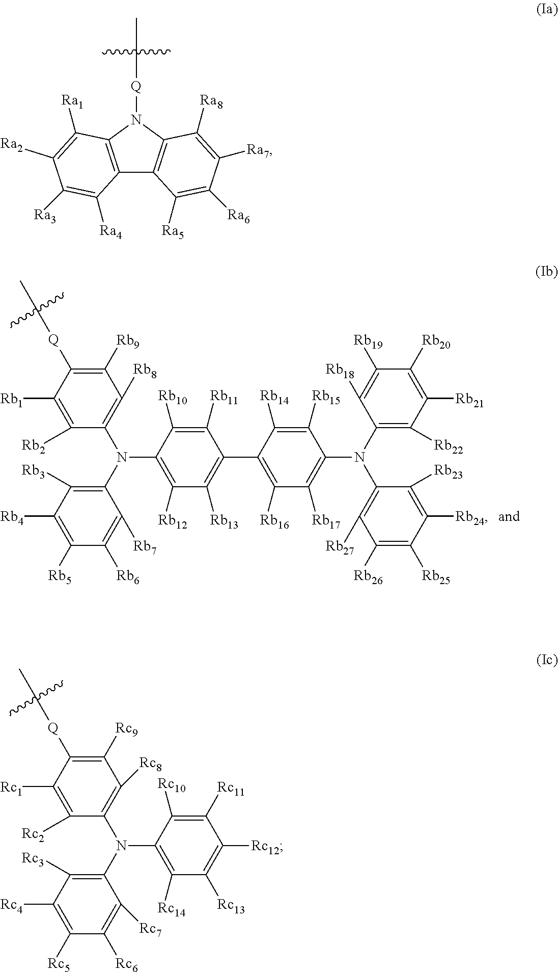
CROSS-REFERENCE TO RELATED APPLICATIONS[0001]This application claims priority to U.S. Provisional Application Ser. No. 61 / 106,835 filed on Oct. 20, 2008, entitled “OPTICAL DEVICES FOR MODULATING LIGHT OF PHOTOREFRACTIVE COMPOSITIONS WITH THERMAL CONTROL,” the contents of which are hereby incorporated by reference in their entirety.BACKGROUND OF THE INVENTION[0002]1. Field of the Invention[0003]The invention relates to an optical device comprising a photorefractive layer that includes a photorefractive composition and at least two inert layers. The photorefractive composition comprises a sensitizer and a polymer that includes a first repeating unit comprising a moiety selected from the group consisting of a carbazole moiety, a tetraphenyl diaminobiphenyl moiety, and a triphenylamine moiety. Embodiments of the composition can be used in optical applications, including holographic data storage and / or image recording materials.[0004]2. Description of the Related Art[0005]Photorefractivi...

Claims


Application Information

Patent Timeline
IPC IPC(8): G02F1/19G02B1/12
CPCG03H1/02G11B7/244G03H2260/54G03H2260/12G11B7/245
Inventor GU, TAOLIN, WEIPINGWANG, PENGFLORES, DONALDYAMAMOTO, MICHIHARU
Owner NITTO DENKO CORP
Learn More