

Carbon-fiber-precursor fiber bundle, carbon fiber bundle, and uses thereof
a technology of precursor fiber and carbon fiber, which is applied in the direction of lighting and heating apparatus, instruments, furniture, etc., can solve the problems of voids and insufficient cost reduction, and achieve the effects of excellent spreadability, excellent productivity, and large value of single fiber fineness
- Summary
- Abstract
- Description
- Claims
- Application Information
AI Technical Summary
Benefits of technology
Problems solved by technology
Method used
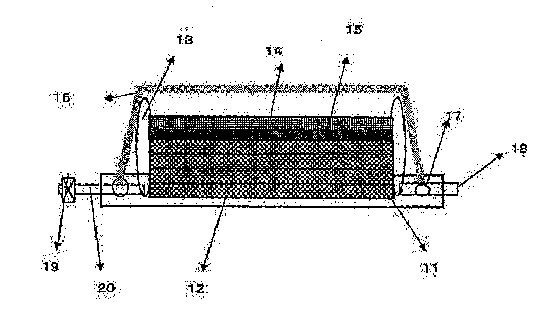
Image

Examples
example 1
[0297]To a 80 liter aluminium polymerization kettle equipped with a turbine agitator wing (agitator wing: 240φ, 4 wings of two steps of 55 mm×57 mm), 76.5 L of deionized exchange water was added to reach an over flow spout of the kettle, 0.01 g of ferrous sulfate (Fe2SO4.7H2O) was added, pH of the reaction was adjusted to 3.0 using sulfuric acid, and the temperature in the polymerization kettle was kept at 57° C.
[0298]Subsequently, ammonium persulfate at 0.10 mol %, ammonium hydrogen sulfide at 0.35 mol %, ferrous sulfate (Fe2SO4.7H2O) at 0.3 ppm and sulfuric acid at 5.0×10⁻² mol %, which were redox polymerization initiators for the monomer were dissolved in deionized exchange water, respectively. These solution were continuously supplied from 50 minutes before starting the polymerization, agitation was performed at an agitation speed of 180 rpm and an agitation power of 1.2 kW / m3, and the average retention time of the monomer in the polymerization kettle was set to be 70 minutes.
[0...
examples 2 to 15
[0305]Copolymers A, B, C or F, G were obtained in the same manner as in Example 1, except that a supply ratio (molar ratio) of the monomers upon start of the polymerization was changed as shown in Table 1 or Table 2. HPMA and HEA in Table 1 or 2 are 2-hydroxypropyl methacrylate and 2-hydroxyethyl acrylate, respectively. The composition, the specific viscosity, the melting point under heat and humidity of the obtained copolymers, and the water contact angle and the oxidation depth De of the film obtained from each copolymer are shown in Table 1 or Table 2.
[0306]A spinning neat solution was prepared using each of these copolymers and the threads were spun in the same manner as in Example 1 to obtain a precursor fiber bundle. The single fiber fineness, the filament number, the fiber density, the coagulation bath condition, the roundness, the cross-sectional shape, the heat quantities Ja and Jb of each precursor fiber bundle are shown in Table 1 or Table 2.
[0307]Then, the flame-proof tr...
example 16
[0324]An acryl-based copolymer A containing 98.0 mol % of the AN unit and 2.0 mol % of the HEMA unit and having the specific viscosity of 0.21 produced in the same manner as in Example 1 was dissolved in dimethylacetamide to prepare a spinning neat solution where the polymer concentration was 21% and a neat solution temperature was 60° C. Threads were spun by the wet spinning method using this spinning neat solution. A coagulation bath into which the spinning neat solution is discharged is an aqueous solution of dimethylacetamide at a concentration of 45% by mass at temperature of 25° C. The number of holes in a spinning nozzle used is 3000. Coagulated threads obtained by coagulating in the coagulation bath were stretched with washing and stretched with heat to total 7.4 times to obtain a precursor fiber bundle A. A discharge amount was controlled so that the single-fiber fineness of the precursor fiber bundle A was 2.5 dtex. The calorific value obtained by the heat flux type differ...
PUM
| Property | Measurement | Unit |
|---|---|---|
| mol % | aaaaa | aaaaa |
| mol % | aaaaa | aaaaa |
| melting point | aaaaa | aaaaa |
Abstract
Description
Claims
Application Information