

Insulated thermal interface material
a thermal interface and material technology, applied in the direction of laminated elements, light and heating equipment, chemistry equipment and processes, etc., can solve the problems of poor heat resistance, inability to withstand the impact, and the duration of components is bad, so as to improve the heat resistance and moisture tolerance, the effect of increasing the cost of the thermal interface material
- Summary
- Abstract
- Description
- Claims
- Application Information
AI Technical Summary
Benefits of technology
Problems solved by technology
Method used
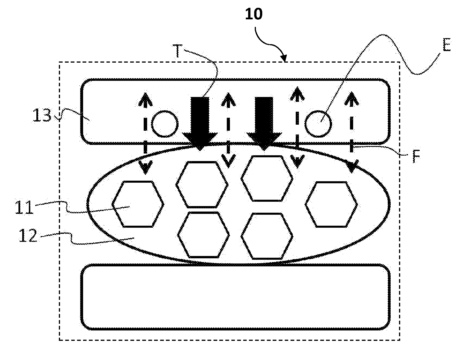
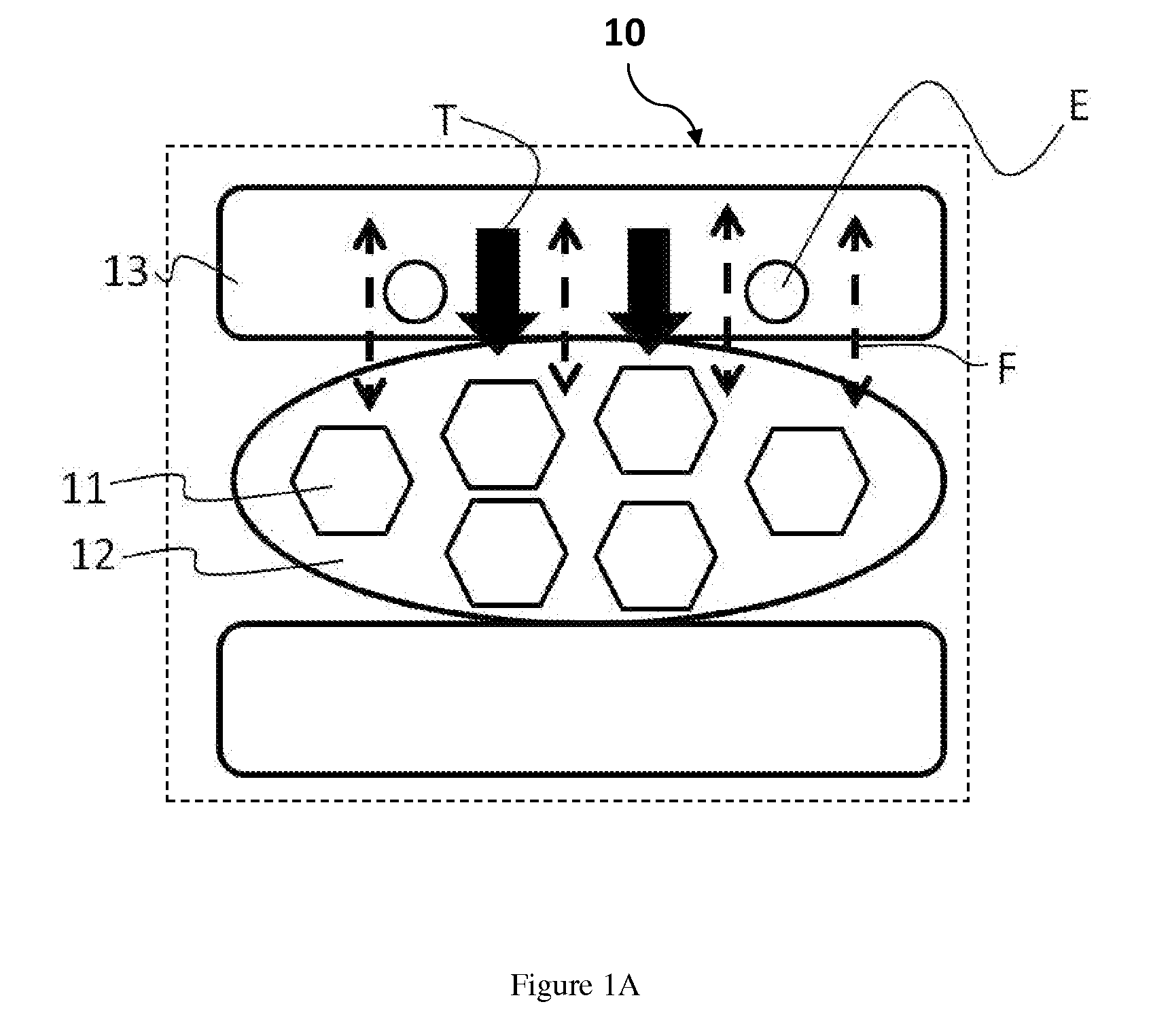
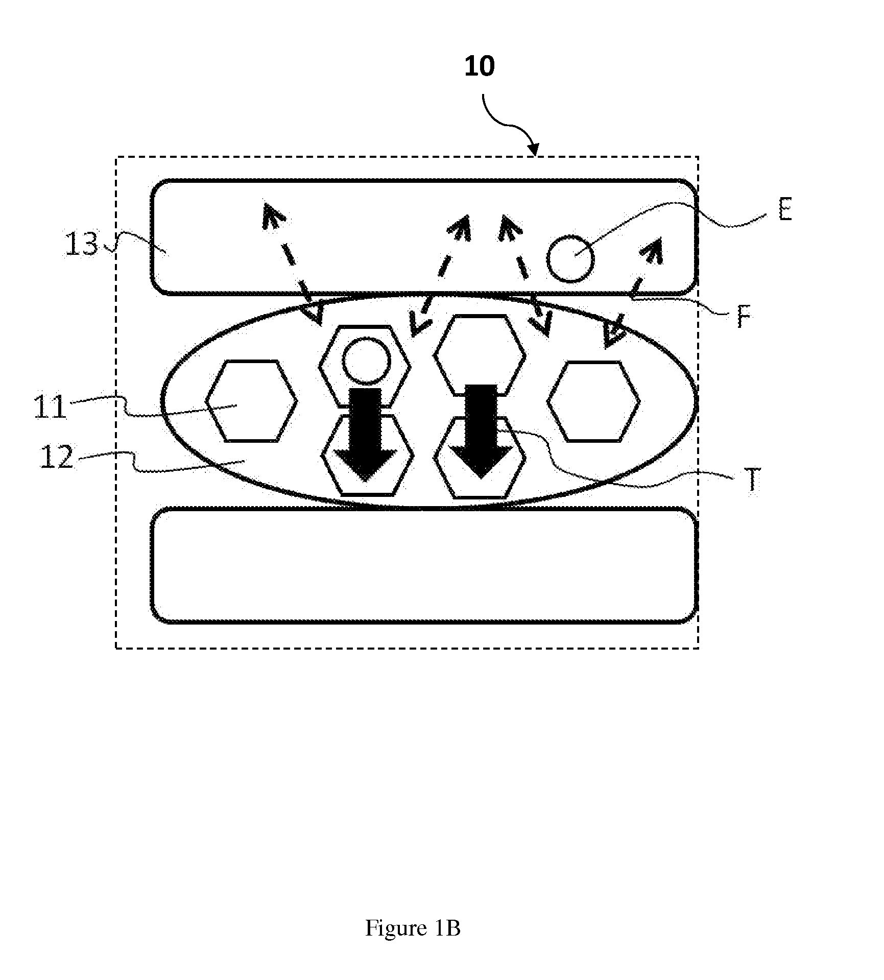
Image

Examples
first embodiment
[0041]In the first embodiment, the base is a silicone rubber and at least contains an organic polysiloxane compound, a curing agent and an adhesion promoter.
[0042]Preferably, the organic polysiloxane compound has a polymerization degree of between 200˜12000 and can be represented by the following formula (I):
R1aSiO(4-a) / 2 (I)
[0043]In the formula (I), R1 is a single-valence C1˜C10 hydrocarbon group and selected from a group consisting of an alkyl group, a cycloalkyl group, an aryl group, an aralkyl group, an alkyl group substituted by halogen and an alkenyl group. Preferably, “a” further represents a positive number of 1.9-2.05.
[0044]Moreover, when R1 is an alkyl group, it could be methyl, ethyl, propyl, butyl, pentyl, hexyl, heptyl, octyl, nonyl or decyl group. When R1 is a cycloalkyl group, it could be cyclopentyl or cyclohexyl group. When R1 is an aryl group, it could be phenyl, tolyl, xylyl or naphthyl group. When R1 is an aralkyl group, it could be phenethyl or hydrocinnamyl g...
second embodiment
[0071]According to a second embodiment of the present invention, the base is a curing epoxy resin and it could be selected from a group consisting of a linear polyepoxide with epoxide as an end group, a polyepoxide with epoxide at backbond and a polyepoxide with epoxide as side chain. It can comprise the following compound represented by the formula (III):
[0072]In the formula (III), R′ is an alkyl group, alkyl ether or aryl group, n is an integer of 2-6. Preferably, the abovementioned curing epoxy resin at least contains two epoxide groups within every molecule and the average molecular weight is 150-10000.
[0073]The epoxy resin includes aromatic glycidyl ether (by reacting of polyphenol with excess amount of epichlorohydrin), cycloaliphatic glycidyl ether, hydrogenation of the glycidyl ether, and their mixture. The polyphenols includes resorcinol, pyrocatechol, hydroquinone and polycyclic phenol including p,p′-dihydroxy benzyl, p,p′-dihydroxy biphenyl, p,p′-dihydroxyphenyl sulfone, ...
PUM
| Property | Measurement | Unit |
|---|---|---|
| glass transition temperature | aaaaa | aaaaa |
| specific gravity | aaaaa | aaaaa |
| thermal | aaaaa | aaaaa |
Abstract
Description
Claims
Application Information