ELECTROLESS DEPOSITION OF Bi, Sb, Si, Sn, AND Co AND THEIR ALLOYS

a technology of electroless deposition and alloys, applied in the direction of electrode manufacturing processes, liquid/solution decomposition chemical coatings, cell components, etc., can solve the problems of structural disintegration of anode materials, crack formation, and high energy density materials that are prone to excessive expansion, etc., to achieve easy scalable, short reaction time, and less waste

Inactive Publication Date: 2015-08-06
MANIVANNAN AYYAKKANNU +1
View PDF6 Cites 23 Cited by
  • Summary
  • Abstract
  • Description
  • Claims
  • Application Information

AI Technical Summary

Benefits of technology

[0016]The method disclosed herein is directed to the preparation of composite materials through formation of coatings of bismuth, antimony, silicon, tin, and cobalt, as well as their various compositional alloys onto copper, brass, carbon, and silicon substrates using electroless deposition. The method disclosed is particularly useful for forming materials with characteristics advantageous for their use in battery electrodes. The method discloses electroless deposi

Problems solved by technology

However, these higher energy density materials are prone to excessive expansion during lithium intercalation, as much as three times their original volume in the case of silicon.
This extreme expansion and contraction during cycling leads to structural disintegration of the anode material.
The repeated volume changes associated with the alloying and dealloying of the metallic anodes with lithium, lead to crack formation and consequent structural degradation of the anode.
The crack formation essentially breaks the electrical contacts within the anode.
Consequently, there is a resulting rapid capacity decay during cycling.
Past attempts to synthesize the materials described have either not been successful and/or rely on undesirable methods of production.
Techniques previously used to produce composite materials have relied on methods that are time consuming, energy demanding, or are not environmentally friendly.
Incorporation of secondary materials to prevent structural decomposition using methods such as chemica

Method used


Image

  • ELECTROLESS DEPOSITION OF Bi, Sb, Si, Sn, AND Co AND THEIR ALLOYS
  • ELECTROLESS DEPOSITION OF Bi, Sb, Si, Sn, AND Co AND THEIR ALLOYS
  • ELECTROLESS DEPOSITION OF Bi, Sb, Si, Sn, AND Co AND THEIR ALLOYS

Examples


example 1

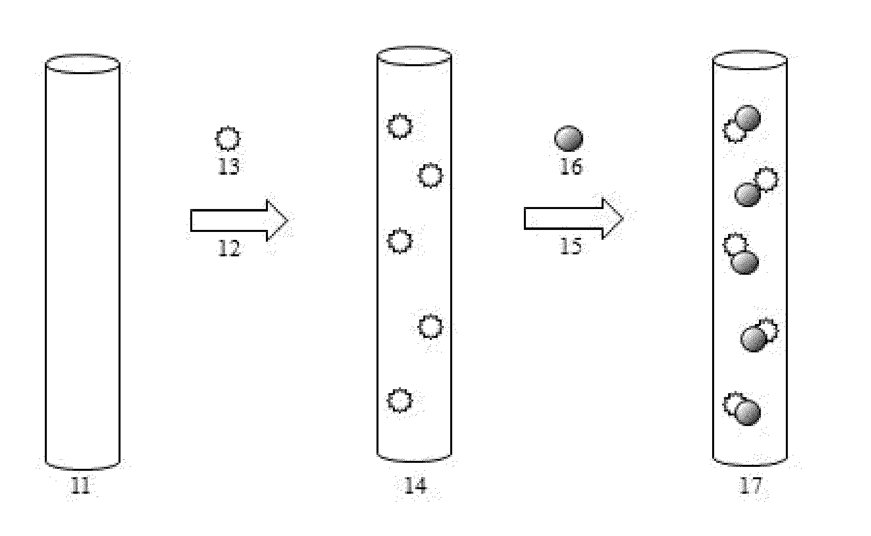
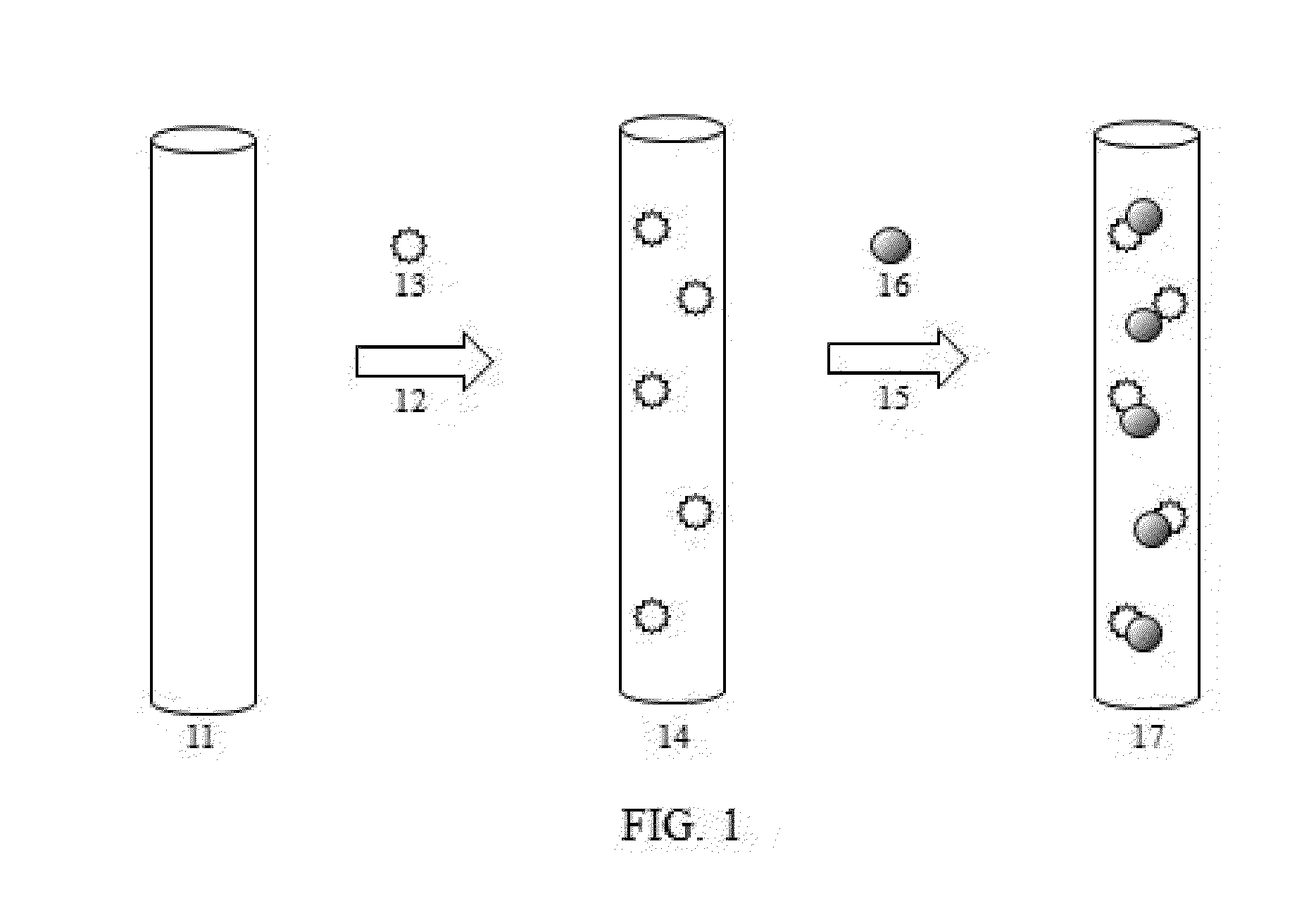
[0040]Electroless deposition of bismuth on brass foil in ethylene glycol: An electroless deposition solution of bismuth was prepared as follows. A solution of 0.1M bismuth chloride in ethylene glycol was prepared by addition of the bismuth chloride to the solvent. The solution was formed at 80° C. with stirring until the solution was clear.

[0041]Next, brass foil was prepared by etching in dilute nitric acid followed by washing in deionized water. Plating tape was then placed over portions of the foil in order to prevent deposition on those areas as a control.

[0042]The brass foil was then immersed for two minutes in the stagnant electroless deposition solution maintained at 80° C. The foil was then removed from the solution and washed of the solution in acetone. The foil was allowed to air dry.

[0043]The present inventors found the color appearance of the foil had changed from brass to lustrous silver. The inventors confirmed the resulting deposition using various techniques including...

example 2

[0044]Electroless deposition of antimony on copper nanoparticles in ethylene glycol. An electroless deposition solution of antimony was prepared as follows. A solution of 0.1M antimony chloride in ethylene glycol was prepared by addition of the antimony chloride to the solvent. The solution was formed at 80° C. with stirring until the solution was clear.

[0045]While stirring the clear solution, 1 gram micron size particles of copper was added to the solution. The particle / deposition solution was agitated for five minutes with intermediate ultra-sonication and vigorous agitation. After the period of immersion, the particles were filtered from the solution, washed with acetone, and allowed to air dry.

[0046]The present inventors found the color appearance of the particles had changed from red to a rust color, indicative of the deposition of antimony onto the copper nanoparticles.

example 3

[0047]Electroless deposition of bismuth and antimony on copper foil: An electroless deposition solution of antimony and bismuth was prepared as follows. A solution of 0.1M antimony chloride and 0.1M bismuth chloride in ethylene glycol was prepared by addition of the antimony chloride and bismuth chloride to the solvent. The solution was formed at 80° C. with stirring until the solution was clear.

[0048]Next, copper foil was prepared by etching in dilute nitric acid followed by washing in deionized water. Plating tape was then placed over portions of the foil in order to prevent deposition on those areas as a control.

[0049]The copper foil was then immersed for 20 minutes in the stagnant electroless deposition solution maintained at 80° C. The foil was then removed from the solution, washed in acetone, and allowed to air dry.


PUM

PropertyMeasurementUnit
Temperatureaaaaaaaaaa
Timeaaaaaaaaaa

Abstract

The present invention relates to production of composite materials utilizing an electroless deposition method for coating substrates with bismuth, antimony, tin, silicon, cobalt and their various compositional alloys. Substrates may be materials comprised of copper, brass, carbon, and silicon. These substrates are immersed in aqueous or ethylene glycol based solutions containing soluble ions of the desired coating material. The present invention generates desired coatings at room temperature during a period of immersion of one hour or less. In one exemplary embodiment, the method provides the electroless deposition of silicon onto copper nanoparticles in a room temperature solution of ethylene glycol. The coated nanoparticles may then be processed to form a battery electrode. In another exemplary embodiment, the method provides electroless deposition of tin onto brass foil in a room temperature aqueous solution. Battery electrodes may then be punched from the coated sheet.

Description

GOVERNMENT INTERESTS[0001]The United States Government has rights in this invention pursuant to the employer-employee relationship of the Government to the inventors as U.S. Department of Energy employees at the National Energy Technology Laboratory.FIELD OF THE INVENTION[0002]The disclosure relates to the production of composite materials utilizing an electroless deposition process to produce films of bismuth, antimony, silicon, tin, and cobalt individually as well as their various compositional alloys directly onto various substrate materials of copper, brass, carbon, and silicon. These methods are particularly useful in forming composite and alloy films on materials for use in applications such as battery anodes in lithium, sodium, and magnesium batteries.BACKGROUND OF THE INVENTION[0003]Current lithium batteries most often use carbon graphite as the anode electrode and have a theoretical energy density of 372 mAh / g. The energy density of the anodes in practice approaches only 20...

Claims


Application Information

Patent Timeline
IPC IPC(8): H01M4/1395C23C18/31C23C18/16H01M4/1393H01M4/04
CPCH01M4/1395H01M4/1393H01M4/0402C23C18/31C23C18/1639C23C18/1651C23C18/1689C23C18/1637H01M4/0452H01M4/386H01M4/625H01M4/661H01M10/052H01M4/387C23C18/1635C23C18/34C23C18/50C23C18/52Y02E60/10
Inventor MANIVANNAN, AYYAKKANNUBECK, FAITH
Owner MANIVANNAN AYYAKKANNU
Why Eureka
Try Eureka