
Electricity storage device

a technology of electrical energy storage and storage device, which is applied in the direction of electrochemical generators, fuel and secondary cells, organic electrolytes, etc., can solve the problems of increased internal resistance of electrical energy storage device, gas generation and internal shorting due to depletion of electrolyte solution, and the decomposition of organic solvent, etc., to achieve lower solution resistance, lower viscosity, and higher electrical conductivity

Inactive Publication Date: 2017-11-30
HISSHINBO HOLDINGS INC
View PDF4 Cites 1 Cited by
  • Summary
  • Abstract
  • Description
  • Claims
  • Application Information

AI Technical Summary

Benefits of technology

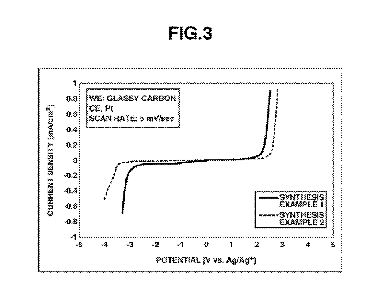
The invention is about an ionic liquid that has lower viscosity and higher electrical conductivity than commonly used ionic liquids in electrical energy storage devices. It also has a higher withstand voltage, which expands the working voltage range of these devices. Additionally, this ionic liquid can charge and discharge even in low-temperature environments, leading to improved performance at low temperatures and enabling the use of these devices over a wider range of temperatures.

Problems solved by technology

However, although increasing the rated voltage is essential for improving the capacity of electrical double-layer capacitors and other capacitors, liquid electrolytes obtained by diluting an electrolyte salt with an organic solvent have the drawback that, as the voltage rises, decomposition of the organic solvent occurs.
Also, when used in a high-temperature environment, organic solvents volatilize, leading both to gas generation and to internal shorting due to depletion of the electrolyte solution.
These problems can be resolved by using an ionic liquid alone as the liquid electrolyte, although liquid electrolytes consisting solely of an ionic liquid have a high viscosity, which gives rise to a different problem: an increase in the internal resistance of the electrical energy storage device.
However, it has a low withstand voltage, which means that it cannot be employed in electrical energy storage devices required to have higher voltages.
An additional problem with electrical energy storage devices in which ionic liquids are used is that, in low-temperature environments, the ionic liquid either undergoes a marked rise in viscosity or it solidifies, lowering the device performance.

Method used


Image

  • Electricity storage device
  • Electricity storage device
  • Electricity storage device

Examples


synthesis example 1

Synthesis of MEMP•FSA

[0062]

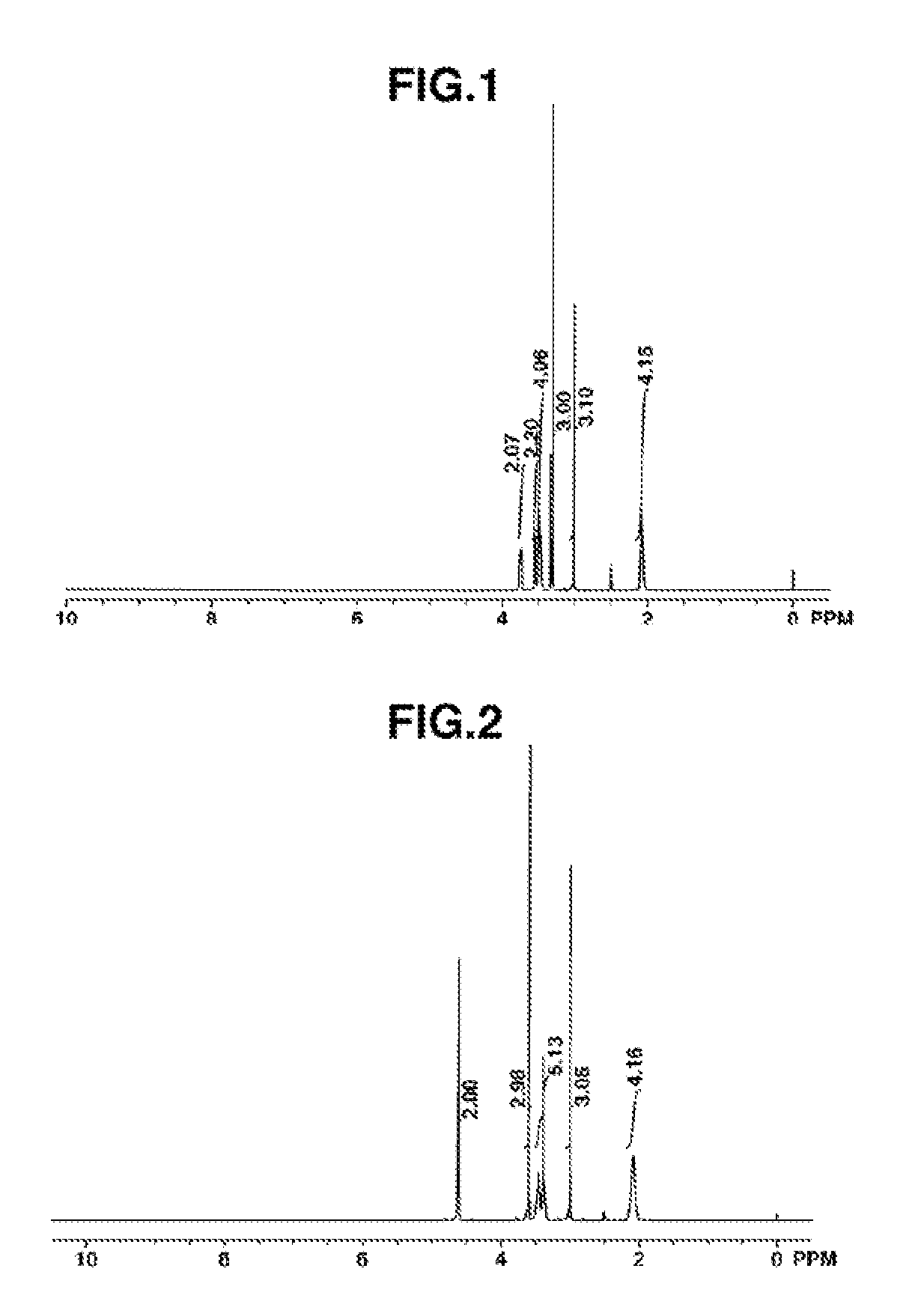
[0063]Pyrrolidine (Wako Pure Chemical Industries, Ltd.), 1.51 parts by weight, and 2-methoxyethyl chloride (Kanto Chemical Co., Ltd.), 1.00 part by weight, were mixed together and reacted for 1 hour under refluxing. Following the reaction, the reaction mixture separated into two layers. When left to cool for a while, the bottom layer solidified. The top layer alone was collected by decantation and purified by vacuum distillation, giving 0.96 part by weight of the target substance N-2-methoxyethylpyrrolidine (boiling point, 76° C.; vapor pressure, 45 mmHg) in a yield of 70%.

[0064]Next, 1.00 part by weight of the N-2-methoxyethylpyrrolidine was mixed with a two-fold volume of toluene (Wako Pure Chemical Industries, Ltd.), the mixture was placed in an autoclave, and the interior of the system was nitrogen purged. The system was closed, after which about 1.00 part by weight of methyl chloride gas (Nittoku Chemicals) was added under stirring at room temperature...

synthesis example 2

Synthesis of MMMP•FSA

[0066]

[0067]A solution of 14.4 parts by weight of N-methylpyrrolidine (Wako Pure Chemical Industries, Ltd.) dissolved in 200 parts by weight of tetrahydrofuran (Wako Pure Chemical Industries, Ltd.) was ice-cooled, and 17.1 parts of chloromethyl methyl ether (Tokyo Chemical Industry Co., Ltd.) was added under stirring. After allowing these to react overnight, the precipitated solids were collected by filtration in vacuo using a Kiriyama funnel. The resulting white solid was dried using a vacuum pump, giving 26.7 parts by weight of the intermediate N-methoxymethyl-N-methylpyrrolidinium chloride (yield, 96%).

[0068]Next, 8.58 parts by weight of the N-methoxymethyl-N-methylpyrrolidinium chloride was dissolved in 10 parts by weight of deionized water. This solution was added under stirring to a solution of 12.5 parts by weight of potassium bis(fluorosulfonyl)amide (Kanto Chemical Co., Ltd.) dissolved in 5 parts by weight of deionized water. Stirring was continued over...

working example 1-1

(1) Production of Positive Electrode Assembly

[0072]A coating slurry for a positive polarizable electrode was prepared by mixing together the activated carbon Maxsorb MSP-20 (Kansai Coke and Chemicals Co., Ltd.), a conductive material (HS-100, from Denka Co., Ltd.) and the binder PVDF (Aldrich Co.) in the weight ratio 85:8:7 within the coating solvent N-methyl-2-pyrrolidone (NMP).

[0073]The slurry was coated on an etched aluminum foil (30B, from Japan Capacitor Industrial Co., Ltd.) as the positive current collector and then rolled using a roll press, following which the NMP was removed by drying so as to form a positive polarizable electrode, thereby giving a positive polarizable electrode assembly.

(2) Production of Negative Electrode Assembly

[0074]A coating shury for a negative polarizable electrode was prepared by mixing activated carbon (LPY039, from Japan EnviroChemicals, Ltd.), a conductive material (HS-100; Denka Co., Ltd.), and the binder PVDF (Aldrich Co.; weight-average mole...


PUM

PropertyMeasurementUnit
temperatureaaaaaaaaaa
boiling pointaaaaaaaaaa
internal pressureaaaaaaaaaa

Abstract

This electricity storage device which is configured to contain an ionic liquid represented by formula (1) in, for example, an electrolyte or an electrode has the advantage of being usable in a low-temperature environment in spite of the ionic liquid contained therein.(In the formula, each of R1 and R2 independently represents an alkyl group having 1-5 carbon atoms; and n represents 1 or 2.)

Description

TECHNICAL FIELD[0001]This invention relates to an electrical energy storage device. The invention relates more particularly to an electrical energy storage device which contains a specific ionic liquid.BACKGROUND ART[0002]By having an ionic liquid serve as an electrolyte, it is possible to use the ionic liquid as a liquid electrolyte without needing to use an organic solvent. Efforts have thus been made in recent years to use, as the electrolyte in electrical double-layer capacitors, an ionic liquid instead of an electrolyte that is a solid salt in which the cation is, for example, a triethylmethylammonium (TEMA) or tetraethylammonium (TEA) ion.[0003]Of such ionic liquids, l-ethyl-3-methylimidazolium tetrafluoroborate (EMIBF4), which includes the tetrafluoroborate anion, is the most common, although art using pyrrolidinium salts, which are alicyclic ammonium salts, as liquid electrolytes is also known (see Patent Documents 1 and 2).[0004]However, although increasing the rated voltag...

Claims


Application Information

Patent Timeline
Patent Type & Authority Applications(United States)
IPC IPC(8): H01G11/62H01M12/08H01M10/0525H01M10/0564H01G11/86H01G11/52
CPCH01G11/62H01G11/86H01M10/0525H01M2300/0045H01M10/0564H01G11/52H01M12/08H01M10/0569H01M10/0568Y02E60/10Y02E60/13
Inventor YUYAMA, KANAKOMASUDA, GEN
Owner HISSHINBO HOLDINGS INC
Learn More