These large forms are slow, heavy, and bulky, and, as they are of a fixed shape, they often store (trap) heat, and thus generally have poor heat dissipation.
These prior art systems do not encompass or employ a more uniform heat dissipating
system nor employ external reinforcing containment “sleeves”, nor do they employ, nor disclose an external nor internal reinforcing mesh or net, thus limiting the range of mixes to be slipform printed, and furthermore limit the shapes and sizes of foundations and walls, etc.
These prior art large slip-formers are also primarily limited to horizontal, or near horizontal, casting.
Furthermore, with traditional slip-forming systems, the casts have rigid, straight line contour limitations, particularly regarding the adjustment of the height and
diameter of the slip-form surfaces to cast the desired
diameter of a cast wall, and usually leave a surface having a rough generic blandness of appearance and other esthetic limitations.
The cured mix, having a smooth appearance, is usually recognized as visually unappealing for most applications, so additional surface amendments, such as cladding, are often added to the surface.
These surface amendments consume additional time and materials, and thus increase the overall cost of construction.
This is particularly true in the case of curved concrete structures, such as silos or stacks, in which accuracy of slip-form placement requires the bulky, heavy, expensive equipment, and considerable time and labor required in continuously adjusting, checking and readjusting the slip-former.
Thus, virtually all prior art slip-forms are unsuitable for constructing structures which are to taper and thus increase, or decrease, in cross-section or shape as the height increases.
Therefore, conventional slip-form systems are heavy, slow, unreliable, have limited casting shapes, are not easily adjusted, and are inaccurate and costly and thus are generally unsatisfactory, particularly when constructing any structures other than simple shapes.
The prior art full-scale 3D construction printing is generally limited to horizontal layer-wise deposition, and furthermore is limited to straight compression walls (straight vertical).
Additionally, almost all prior art 3D printing systems are limited to multi-pass construction, which looks like corrugated
cardboard and has several significant structural, aesthetic, and time and labor limitations.
Additionally, within the prior art, constructing structures having complex multi-curved walls, particularly constructing with multiple temporary curved concrete forms for casting concrete walls, particularly those with small radiuses, is problematic and is cost prohibitive.
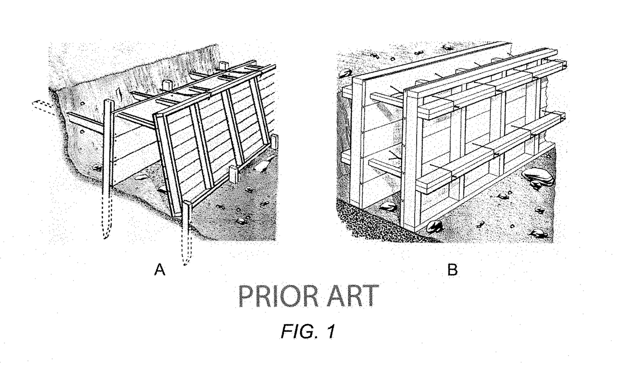
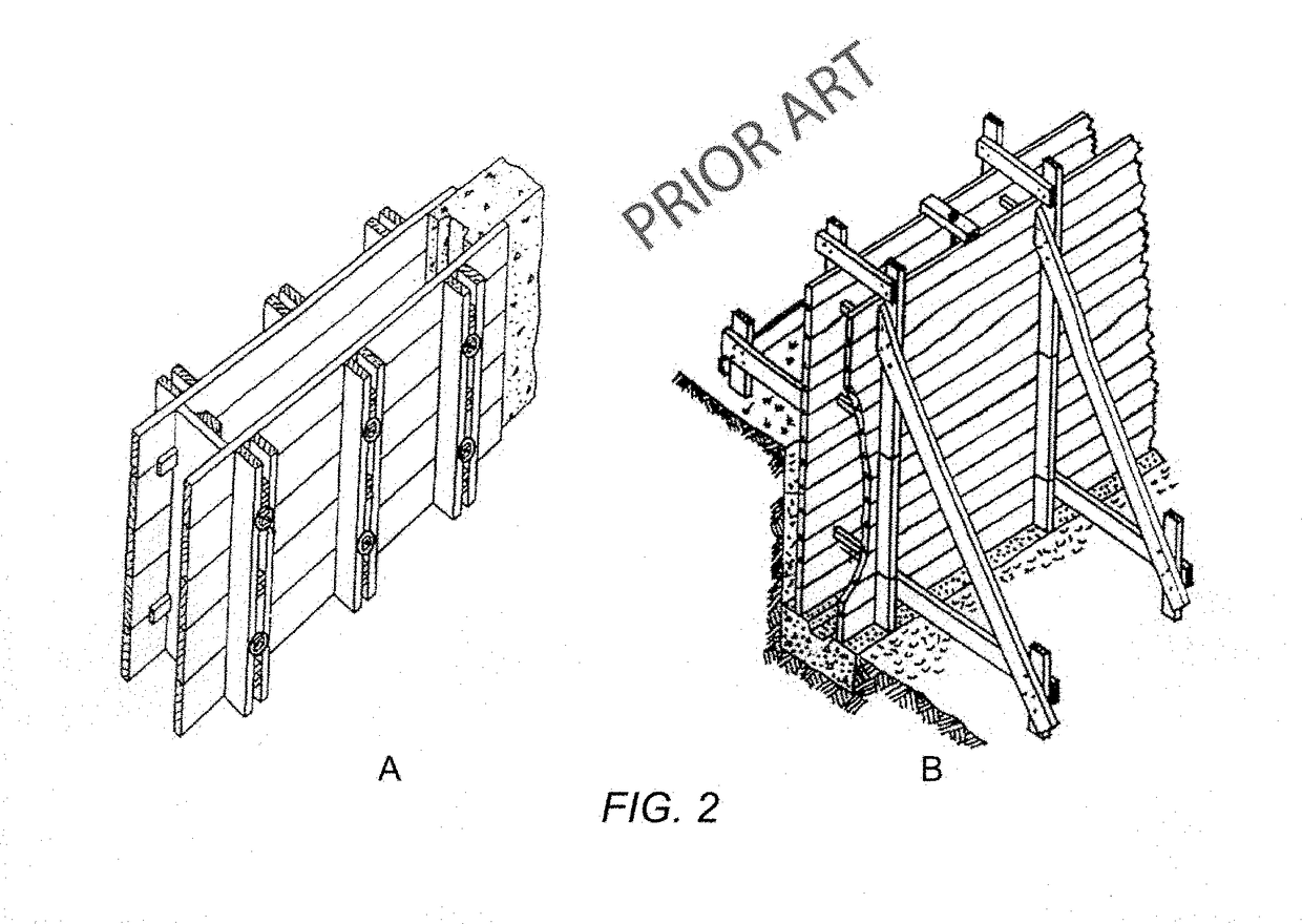
Materials such as reinforced concrete can be molded into curved structures, however conventional systems require costly individualized concrete forms to shape and support such materials in their initial fluid or plastic state.
Assembly of wooden forms in complex curved shapes requires a great expenditure of materials, cost, time, and effort.
Structures built from conventional wood frame materials generally have relatively low energy efficiency and require a high level of maintenance.
And tend to be fragile, and are susceptible to damage from storms, floods, earthquakes, and fire than are other reinforced concrete structures with curvilinear geometries.
However, the construction of such full 3-dimensional full architectural scale printed curvilinear structures has previously been unwanted or problematic and cost prohibitive.
Many prior art curvilinear construction system traditionally used such as Binishells, geodesic domes, air form structures, etc. have significant design limitations, and often have a
critical phase of construction, and often requires large, expensive, specialized equipment.
Furthermore, the system often requires a narrow and specific cementitious mix and costly
specialty made molding systems.
The prior art includes free-form 3D printing of custom formworks, such as
Branch Technology, Freefab, AI Build, and Mesh-Mould, which have significant limitations of time and post
processing requirements, such as not disclosing nor teaching single-pass construction.
WO2015065936A2 and PCT / US2014 / 062514 of
Branch Technology discloses employing a movable extruder places extrudate that solidifies in open space to create “scaffolding” or “skeletons” of structures and other products, such as custom concrete formworks, however is limited to printing in multiple sections of 3D walls off site, that further require onsite post filling with filler material such as polymeric insulating foam, and requires shipping and manual installation onsite, with additional post
processing such as being coated with traditional materials and employing conventional prior art techniques for completion.
These skeletonized construction systems do not disclose or teach onsite slip-form printing of reinforced cementitious materials, nor do they disclose optimizing the curing / casting environment to optimize the mix properties and characteristics nor use of an external reinforcement sleeve, nor do they disclose nor teach compatibility with conventional reinforcement.
Additive manufacturing processes such as
full scale 3D printing have been proposed and extensively used for the manufacture of many small-scale items (generally limited to about 1 mm to 500 mm), though difficulties have been encountered in using such processes for the manufacture of larger scale items (BAAM—Big Area Additive Manufacturing and Large Scale Additive Manufacturing), such as complete buildings, panels, and other full architectural scale 3D printing, which presently can be
time consuming and labor intensive to form.
Also, some items previously formed with 3D printing processes have lacked sufficient structural strength for use in applications having minimum strength requirements or in applications having the requirement to satisfy the relevant
Building Code of Construction that is applicable to a construction project.
Furthermore, prior art 3D printing processes are generally not suitable for onsite manufacturing of large full architectural scale structures or for creating cladding components on any architectural scale.
While Computer
Numerical Control (CNC) machines can operate on large objects, CNC machines impose severe limitations on the geometries and materials of the work pieces.
Increasingly, customers are demanding more complex and difficult to construct full architectural scale structures, for example, large scale structures with highly complex curvilinear designs or are made of composite materials.
Thus, the fundamental limitations of automated digital construction technologies and
mass construction systems currently known in the prior art limit the extent to which these systems can provide solutions as per the limitations outlined above.
Furthermore, disposal of
construction waste materials is a significant cost in the
construction industry, however, with 3D printing only the necessary construction materials for each project are produced.
It takes about 24 hours for the material to completely harden.
The patent does not disclose nor teach employing an external moldable reinforcement sleeve.
This patent does not disclose nor teach how to print full architectural scale reinforced standardized nor large bricks, nor using a slip-form printer employing a variety of different scalable, quickly interchangeable or custom dyes or molds to print a variety of customized
interlocking brick shapes and configurations such as but not limited to having external reinforced interlocking layer-wise keyway(s).
Furthermore, this patent does not disclose nor teach how to construct foundations nor roofs nor compatibly install major elements of construction process of a regular building, such as electrical services,
piping and plumbing, conduits,
doors, windows, joinery and finishes within the structure, nor the ability to make last minute on site construction changes.
The patent does not disclose nor teach employing an external reinforcement sleeve.
This patent does not disclose nor teach how to print full architectural scale reinforced standardized nor large bricks, nor using a slip-form brick printer system employing a variety of different scalable, quickly interchangeable or custom dies or molds to print a variety of customized interlocking brick shapes and configurations such as but not limited to having external reinforced interlocking layer-wise keyway(s).
Furthermore this patent does not disclose nor teach how to construct roofs nor compatibly install major elements of construction process of a conventional building, such as electrical services,
piping and plumbing, conduits,
doors, windows, joinery and finishes within the structure, nor the ability to make last minute on site construction changes.
The patent does not disclose nor teach employing an external reinforcement sleeve nor how to print full architectural scale reinforced standardized large bricks, nor using a slip-form printer employing a variety of different scalable, quickly interchangeable or custom dies or molds to print a variety of customized interlocking brick shapes and configurations such as but not limited to having external reinforced interlocking layer-wise keyway(s).
Furthermore, this patent does not disclose nor teach how to construct roofs nor compatibly install major elements of construction process of a standard building, such as electrical services,
piping and plumbing, conduits,
doors, windows, joinery and finishes within the structure, nor the ability to make last minute on site construction changes, nor having additional operating and or transportable platforms.
The patent does not disclose nor teach employing an external reinforced sleeve.
This patent does not disclose nor teach how to print full architectural scale reinforced bricks, nor using a slip-form printer employing a variety of different scalable, quickly interchangeable or custom dies or molds to print a variety of reinforced interlocking brick shapes and configurations such as but not limited to having external reinforced layer-wise interlocking keyway(s).
Furthermore, this patent does not disclose nor teach how to construct roofs nor compatibly install major elements of construction process of a standard building, such as electrical services, piping and plumbing, conduits, doors, windows, joinery and finishes within the structure, nor the ability to make last minute on site construction changes.
The patent does not disclose nor teach employing an external reinforcement sleeve.
This patent does not disclose nor teach how to print full architectural scale reinforced standardized nor large bricks, nor using a slip-form printer employing a variety of different scalable, quickly interchangeable or custom dies or molds to print a variety of customized interlocking brick shapes and configurations such as but not limited to having external reinforced interlocking layer-wise keyway(s).
Furthermore, this patent does not disclose nor teach how to construct roofs nor compatibly install major elements of construction process of a standard building, such as electrical services, piping and plumbing, conduits, doors, windows, joinery and finishes within the structure, nor disclose the ability to make last minute on site construction changes.
The patent furthermore does not disclose printing in additional angles employing a 6 degree of freedom automated robotic arms.
This method limits the height of any structure constructed, to the reach of the combined boom and
dipper stick.
The patent does not disclose nor teach employing an external reinforcement sleeve.
This patent does not disclose nor teach how to print full architectural scale reinforced standardized nor large bricks, nor using a slip-form printer employing a variety of different scalable, quickly interchangeable or custom dies or molds to quickly print a variety of customized interlocking brick shapes and configurations such as but not limited to having external reinforced layer-wise interlocking keyway(s).
Furthermore, this patent does not disclose nor teach how to construct roofs nor compatibly install major elements of construction process of a conventional building, such as electrical services, piping and plumbing, conduits, doors, windows, joinery and finishes within the structure, nor the ability to easily make last minute on site construction changes.
This patent does not disclose nor teach how to print reinforced standardized nor large bricks, nor does it disclose using a slip-form printer nor employing a wide variety of different interchangeable or custom dies or molds to print a variety of customized bricks shapes and configurations such as but not limited to having external reinforced interlocking layer-wise keyway(s).
Furthermore, this patent does not disclose nor teach how to compatibly install major elements of the construction process of a regular building, such as electrical services, piping and plumbing, conduits, doors, windows, joinery and finishes within the structure, nor does it disclose the ability to make last minute on site construction changes.
This patent does not disclose nor teach how to print full architectural scale reinforced standardized nor large bricks, nor using a slip-form printer employing a variety of different scalable, quickly interchangeable or custom dies or molds to print a variety of customized interlocking brick shapes and configurations such as but not limited to having external reinforced interlocking layer-wise keyway(s).
Furthermore, this patent does not disclose nor teach how to construct roofs nor compatibly install major elements of construction process of a regular building, such as electrical services, piping and plumbing, conduits, doors, windows, joinery and finishes within the structure, nor the ability to make last minute on site construction changes.
Furthermore, including constructing
mass customized “pieces” that require transportation and
assembly onsite into the structure and requires production in an off-site construction facility and transport, with further manual labor required for assembling of each individual wall panel then manually
coating with concrete and insulation into the larger building's form.
This patent does not disclose nor teach how to print reinforced standardized nor large bricks, nor does it disclose using a slip-form printer nor employing a variety of the same or a wide variety of different interchangeable or custom dies or molds to create a variety of customized brick shapes and configurations such as but not limited to having external reinforced layer-wise interlocking keyway(s).
Furthermore, this patent does not disclose nor teach how to compatibly install major elements of the construction process of a regular building, such as electrical services, piping and plumbing, conduits, doors, windows, joinery and finishes within the structure, nor does it disclose the ability to make last minute on site construction changes.
This gantry, which must be assembled onsite with the aid of a crane, and having two crane-like arms and a large crossbeam which carries the large and bulky
cement printing head having a generally round
extrusion nozzle, with the entire printing
machine sliding along a set of large tracks, and is estimated to take about a week to assemble onsite, and significant time and complexity (requires a crane) to disassemble, thus having an extremely high initial
purchase cost and having a highly inefficient economy of scale.
Due to Khoshnevis
large size gantry's, expensive cost, difficulty of transport,
time consuming assembly and disassembly on the construction site, note the spans and scaling of the gantry system that is larger than the structure to be constructed and further requires the use of aluminum, steel, composites materials, etc. that is sufficient to prevent the flexing of its structural members, and thus results in added weight of the guiding members.
Furthermore, maintaining the rigidity of the long external gantry bridge is crucial especially during acceleration and decelerations in the X-axis direction (such as at the beginning and ending of printing walls) and this method currently produces a rough non-esthetic desirable finish and is not easily adjusted on the construction site.
Additionally, the extensive site-preparation, such as requiring the site to be almost completely level, and the transport and setup of the large,
heavy equipment required by the Khoshnevis system would make constructing in remote areas difficult or even impossible.
Also, material delivery to such large gantry systems, which move in a large volume in the three-dimensional space, have proven to be difficult to implement.
Furthermore, delivery of cementitious materials to the round dispensing
nozzle, given the localized motions of the
nozzle (rotation and deflections), can also present significant challenges such as but not limited to cable slippage, additionally requiring a very narrow and specific concrete mix and very narrow casting (printing) temperature and
humidity range to overcome highly undesirable cold joint interfaces, and does not allow for generic nor high other performance nor
specialty cementitious mixes.
Onsite, this also makes the Contour Crafting system unsuitable for constructing temporary or emergency structures.
Additionally, the prior art gantry system from Khoshnevis provides only three directions of motion for the
cement mix casting materials transport and having a generally round delivery nozzle.
However, for the
cement mix delivery nozzle to print various geometrical features (such as small radiuses such as corners,
stairs, curves, etc.) is highly problematic or even impossible.
Contour crafting, and many other prior art systems, is limited to straight compression (straight vertical) wall(s) layerwise construction, and does not disclose nor teach employing an external reinforced slipform molded printed brick having an interlocking keyway.
Additionally, Khoshnevis' system is currently only capable of cold joint casting without slippage (drool) even in a factory environment.
Furthermore, Khoshnevis' Contour Crafting is prone to excess motions, limited deployment and is prone to torqueing, particularly in windy conditions, also requiring long cement feeding hoses and only prints from overhead or from the outside in (extremely inefficient), and can only print (construct) on flat lots or sites (locations) that do not have trees, power lines, or any other commonly encountered onsite obstacles.
In addition to these and other significant limitations, the Khoshnevis construction system does not disclose or teach construction of foundations nor roofs, and can only construct limited geometries (generic structures) having simple flat walls and cannot print complex shaped structures.
A further limitation is that Khoshnevis system does not allow for a variety of standard nor progressive reinforcements, and their disclosed concrete mix does not disclose employing structurally reinforced concrete, nor conventional reinforcement bars, rods, or cables, or micro-reinforcements, particularly when a printing with generally round nozzle having small radii and / or complex curves.
Furthermore, this prior art apparatus (Reference FIG. 6) does not sufficiently compensate for the inconsistencies encountered from the differences in cementitious mixes and actual pumping rates, and is unable to easily compensate for any last minute onsite printing changes during the construction process, particularly when construction in windy or in inclement weather, and is further limited to a
narrow range of wall shapes, thicknesses and heights, and is further limited to ‘printing’ rough wall surfaces with rough joints, and is generally impractical for remodeling or
retrofitting pre-existing structures.
Contour Crafting does not disclose nor teach employing a flexible, moldable external nor internal reinforcing containment sleeve having pre-engineered curing controlling methods nor apparatuses on one or more sides.
This prior art technology may only be cost effective on a
mass commercial basis, such as very level (flat) open desert
terrain, or may only be practical when repeatedly constructing virtually the same design as this printing system requires accurate onsite grading, and does not teach nor disclose automatically compensating for any onsite ground irregularities, such as when constructing a foundation, and can only print straight compression structures, (vertical flat walls) and requires specialized cementitious mixes.
As Khoshnevis is unaware of or ignores the necessary and required control of the cementitious curing environment particularly to eliminate cold joints and is limited to a narrow and specific range of printing environments, such as onsite temperature,
humidity, the mixes
viscosity /
slump, and is prone to clogging.
Nor does any of the prior art disclose nor teach printing internal reinforcement cables nor internal reinforcing nets.
As Khoshnevis does not employ an external containment sleeve, the patent is not able to sufficiently compensate for cementitious mixes
slump inconsistencies such as the extruded bricks edge collapsing, ripples, and other distortions, even in a factory having controlled environmental conditions, thus printing a highly undesirable rough aesthetic appearance.
However, for certain cementitious printing mixes and or cementitious pastes and other printing materials, these prior art 3D printing systems are unworkable on actual onsite construction conditions, as they are too slow in providing accurate automated printing and placement further do not provide a tunable dynamic response, which to remediate would add significantly to the prior art
machine's complexity and cost.
Khoshnevis additionally teaches use of complex post-actuated and computer controlled trowels, however this system has significant limitations in their surface finishes and lack of molding and shaping means, and furthermore requires post-
processing steps.
Furthermore, the prior art construction technology falls far behind current
Computer Design Technology that allows architects to conceive and design highly complex such as biomorphic structures.
Unfortunately, currently existing concrete
full scale 3D printing systems, including the prior art 3D printing systems disclosed herein, do not allow the full potential of these new designs to be achieved.
The patent does not disclose nor teach employing a molded external reinforcement sleeve.
This patent does not disclose nor teach how to print full architectural scale reinforced standardized nor large bricks, nor using a slip-form printer employing a variety of different scalable, quickly interchangeable or custom dies or molds to print a variety of customized interlocking brick shapes and configurations such as but not limited to having external reinforced interlocking layer-wise keyway(s).
Furthermore this patent does not disclose nor teach how to construct foundations, roofs, door frames, window frames, joinery, and other finishes within the structure, nor the ability to make last minute on site construction changes.
Doesn't disclose nor teach employing an external reinforcement sleeve.
This patent does not disclose nor teach how to print full architectural scale reinforced standardized nor large bricks, nor using a slip-form printer employing a variety of different scalable, quickly interchangeable or custom dies or molds to print a wide variety of customized interlocking printed brick shapes and having configurations such as but not limited to external reinforced layer-wise interlocking keyway(s).
Furthermore this patent does not disclose nor teach how to construct roofs nor compatibly install major elements of construction process of a standard building, such as electrical services, piping and plumbing, conduits, doors, windows, joinery and finishes within the structure, nor the ability to make last minute on site construction changes.
This patent further does not disclose nor teach employing a wide variety of
industrial robot arms, and or a variety of transportable and or operating platforms.
While claiming one of the largest 3d printers in the world, Qingdao has an X and Y axis of 12 meters (almost 40 feet) each, and weighs about 120 tons and requires cranes for
assembly and other costly machines, and does not disclose nor teach how to print foundations nor roofs.
This technology shares many of the limitations of the Khoshnevis prior art discussed herein, and furthermore does not disclose nor teach employing an external reinforcement sleeve.
This patent does not disclose nor teach how to print full architectural scale reinforced standardized nor large bricks, nor using a slip-form printer employing a variety of different scalable, quickly interchangeable or custom dies or molds to print a wide variety of customized interlocking printed brick shapes and configurations such as but not limited to having external reinforced interlocking layer-wise keyway(s).
Furthermore, this patent does not disclose nor teach how to construct roofs nor compatibly install major elements of construction process of a standard building, such as electrical services, piping and plumbing, conduits, doors frames, window frames, joinery and finishes within the structure, nor the ability to make last minute on site construction changes.
This patent further does not disclose nor teach employing a wide variety of
industrial robot arms, and or employing a variety of transportable and or operating platforms.
However, many sources have shared that no technology has been disclosed and that the structures were pre-fabricated off-site in a factory in environment in Suzhu China, and then transported and assembled in Shanghai in one day.
While WinSun requires transport and onsite assembly, it also suffers the same limitations of having a very large, heavy gantry 3D house printer.
Such as having heavy, large, bulky heavy components, being expensive to purchase, transport, and install while having narrow and specific range of
usable cementitious mixes, and requiring more precise construction site preparation and inability to deal with common construction site restrictions such as sloped lots, power lines, trees, boulders, and other commonly encountered onsite obstacles.
The patents do not disclose nor teach employing an external reinforcement sleeve.
This patent does not disclose nor teach how to print full architectural scale reinforced standardized nor large bricks, nor using a slip-form printer employing a variety of different scalable, quickly interchangeable or custom dies or molds to print a variety of customized interlocking brick shapes and configurations such as but not limited to having external reinforced interlocking layer-wise keyway(s).
Furthermore, the patents do not disclose nor teach how to construct roofs nor compatibly install major elements of construction process of a standard building, such as electrical services, piping and plumbing, conduits, doors frames, windows frames, joinery and other finishes within the structure, nor the ability to make last minute on site construction changes.
This patent further does not disclose nor teach employing a wide variety of
industrial robot arms, and or a variety of transportable and or operating platforms.
Currently, all disclosed prior art 3D house printers are very large, expensive, and hard to use.
Some limitations are that the Apis Cor printer systems requires
proprietary software, and is limited to a narrow and proprietary concrete and
fiber mix compound, and has a small, slow, small volume printed layer of about 1×1 inch from a generally round nozzle, producing a cold joint bond having a rough unsightly finish requiring additional manual labor, such as troweling.
Furthermore, Chen-Iun-Tai is limited to continuous printing and does not disclose nor teach intermittent printing.
Additionally, Apis Cor has a relatively small printing zone of about 132 square meters, further limiting sizes of constructing (printing) structures; between about 12 ft. by 12 ft, and is unable to print small radiuses, nor are they able to print foundations, roofs, floors, and small rooms onsite.
Apis Cor furthermore requires the use of an expensive onsite crane to move its supporting operating platform within the printed structure or house (each room), and also to remove following printing, and is heavy (about 2.4 tons), making it unsuitable for small scale worksites.
US 20160361834 A1 by Nikita Chen-Iun-Tai is also limited to straight compression printing (vertical walls), and does not disclose nor teach printing a foundation nor roofs, and are further unable to 3D print small separate closets, shelves, benches, storage areas, or hampers, etc.
Apis Cor also requires significant additional construction steps, including a separate process to construct a foundation and requiring significant manual labor onsite prior to printing the structure.
The Chen-Iun-Tai patent is further limited to one operating platform, and multi-pass construction with cold joint interface challenges and wall shapes and size limitations.
US 20160361834 A1 by Nikita Chen-Iun-Tai does not employ an external fabric reinforcing nor containment sleeves, and is limited to a very narrow and proprietary concrete mix and limited printing range in terms of concrete mixes and having a narrow printing temperature and
humidity range, and furthermore their disclosed concrete mix does not disclose employing structural concrete, reinforcement bars, rods, cables, nor micro-reinforcement.
US 20170021527 A1 further does not disclose nor teach how to print full architectural scale reinforced standardized nor large bricks, nor using a slip-form printer employing a variety of different scalable, quickly interchangeable or custom dies or molds to print a variety of customized interlocking brick shapes and configurations such as but not limited to having external reinforced interlocking layer-wise keyway(s).
Furthermore, this patent does not disclose nor teach how to construct roofs nor compatibly install major elements of construction process of a standard building, such as electrical services, piping and plumbing, conduits, doors, windows, joinery and finishes within the structure, nor the ability to make last minute on site construction changes.
This patent further does not disclose nor teach employing a wide variety of industrial
robot arms, and or a variety of transportable and or operating platforms.
Even some of the more promising directions and technologies among the prior art full architectural scale automated 3D House printing construction systems still have a wide variety of significant limitations.
Currently, almost all 3D printers have massive beams and rods moving a massive overhead top-down print head to and fro in
full scale building volumes, and there is a significant cost to all that massive hardware (many tons).
Currently none of these prior art 3D House Printing systems disclose nor teach how to compatibly install major elements of the construction process of a regular building, such as electrical services, piping and plumbing, conduits, door frames, window frames, jointery and other finishes within the structure (excepting Kamermaker and Contour Crafting), nor do they employ any attachment tool(s) such as spray nozzles, sand blasters, grinders, drills,
laser and acoustic leveling, etc.
In summary, virtually all referenced full architectural scale 3D house printing systems are currently very large, expensive, and difficult to operate, offer little or no construction scaling, versatility, particularly in the onsite construction of individual homes, and are unsuitable for small scale worksites such as when constructing hallways, pantries, shelves, closets, bathrooms, etc.
Most of the prior art 3D printing technologies are currently limited to a single scale of building system, and furthermore most are currently limited to pre-fab construction in a factory environment.
This prior art limitation of the 3D construction systems not being scalable is a significant limitation in the implementation of 3D construction printing within the global
construction industry.
Additionally, these systems do not disclose nor teach how to construct freeform structures onsite nor slip-form casting (printing) of temporary components such as constructing temporary supporting arches and (3D-printing) temporary wall sections onsite.
Furthermore, none of these prior art 3D printing systems can construct in inclement weather such as rain driven
snow or high winds nor do they disclose or teach 3D printing roofs.
Other significant limitations of the prior art 3D printing is that almost all require a narrow and specific concrete mix and only extrudes through a slow, low-volume, multi-pass generally round nozzle that extrudes materials producing an undesirable cold
bond interface, and furthermore generally extrudes materials with a rough and uneven surface.
The common prior art practice of extruding from an overhead
extrusion coming out of a generally circular nozzle additionally may create voids in the mix, commonly referred to as honey comb or bug holes, particularly when depositing in a layer-wise manner, thus significantly reducing the bonding and potential
structural integrity of the printing, and is further unable to produce a smooth, or other aesthetically desirable finishes.
In addition, none of the prior art full architectural scale 3D printing systems disclose nor teach onsite nor offsite printing with
specialty mixes such as High Performance, or Ultra-High Performance reinforced concrete mixes, further including memory return concrete mixes, smog absorbing (capturing) concrete mixes, humidity regulating concrete mixes, memory return concrete and EMF and EMP shielding concrete mixes etc.
None of the prior art 3D Printers disclose nor teach printing reinforced standardized nor large bricks, nor using a die or molding slip-former employing a wide variety of different interchangeable or custom scalable dies or molds as needed in the art to print a wide variety of customized brick shapes and sizes such as having the same or different configurations such as but not limited to having external reinforced layer-wise interlocking keyway(s).
Virtually none of the prior art printing systems are able to 3D print contour angles nor printing from a vertical approach and are generally limited to horizontal multi-pass printing of walls that are thus limited to straight compression (vertical walls).
Overhead gantry, and other 3D House Printing applications, are limited to one, generally horizontal, direction of printing.
Thus, these prior art 3D printing apparatuses do not have the sufficient diversity nor
scalability to serve as a full scale onsite architectural construction tool.
Virtually none of the prior art concrete construction printing systems that disclose or teach the onsite printing of monolithic or near monolithic structures (one piece), nor do any of the above disclose nor teach the 3D printing of roofs, nor do any of the above disclose nor teach the construction of reinforced foundations, footings onsite.
Currently there are no prior art full architectural scale 3D printing systems that disclose or teach slip-forming construction from a backhoe, a
truck, a transportable and operating trailer, nor employing a temporary
auger support, nor a permanent cast in place leave in place operating pedestal, nor a light weight transportable operating pedestal(s), nor a light weight reusable operating pedestals, nor any other operating pedestal (except for limited heavy bulky types such as Apis Cor), and virtually no prior art 3D House printing system teaches or discloses employing onsite guide rails that are light weight and transportable.
Note currently most prior art 3D House Printing systems are only able to print wall sections in a factory environment requiring a controlled temperature and humidity environment.
One significant overlooked prior art limitation is that virtually none of the 3D full architectural scale house (structure) printing systems have the ability to make last minute construction changes on site.
In summary, the prior art 3D printing technologies are significantly limited in their construction flexibility and, furthermore, most are not compatible with other conventional construction systems.
The prior art 3D printing technologies are also generally limited to continuous printing and do not teach nor disclose intermittent printing, and furthermore the inventor was unable to find any prior art 3D printing system that was able to print a structure without human intervention.
Note low concrete test strength results in
hot weather are often caused by poor
evaporation protection and improper initial curing environment of test specimens.
Note, printing cementitious mixes, particularly onsite during
hot and humid weather, often causes plastic-shrinkage, surface and interior
cracking,
accelerated curing (setting), increased
slump loss (shrinkage), and decreased mechanical properties, and reduces the structural strength characteristics of the cured mix.
The prior art does not disclose nor teach employing slip-formed printing external molded containment sleeves that resolve the challenge of the cement ‘ink’ rapidly setting with high
adhesive resistance, and further optimizes the mix
phase change control, further optimizing and providing pre-engineered
water vapor diffusion resistance.
Furthermore, the prior art does not disclose nor teach employing slip-form printing external molded containment sleeves that reduce or eliminate long-term leaching (such as slip-form printing mixes containing
fly ash), and shortens the curing rate and thus the time between the printing of each interlocking printed brick
layers, thus optimizing the onsite construction speeds.

