Method for preparing hierarchically porous doped carbon material and its use

Active Publication Date: 2018-07-05
CITY UNIVERSITY OF HONG KONG
View PDF1 Cites 21 Cited by
  • Summary
  • Abstract
  • Description
  • Claims
  • Application Information

AI Technical Summary

Benefits of technology

[0017]The inventors unexpectedly found that the hierarchically porous doped carbon material obtainable by the method of the present invention exhibits outstanding oxygen reduction/oxygen evolution activities with a metric potential difference of 0.72 V in 1 M KOH, the best value for metal-free catalysts reported so far with high stability in different electrolytes. The excellent performances of the hierarchically porous doped carbon material as catalyst were confirmed by the inventors and include good conductivity, abundant accessible dopant species and exceptionally suitable porous architectures. More specifically, the inventors could show that a hierarchically porous N and S dually-doped carbon material prepared by the method of the present invention exhibits comparable or even better ORR activities with regard to the state-of-the-art Pt/C catalyst in both alkaline and acidic electrolytes and outperform most of the efficient metal-free ORR catalysts known so far. Furthermore, the hierarchically porous N and S dually-doped carbon material prepared by the method of the present invention can behave as an OER catalyzer, and its overall bi-functional ORR/OER performance ranks as the best value by metal-free reversible oxygen catalysts reported to date. Moreover, the in

Problems solved by technology

The coupled multi-electron and multi-proton O2 reduction/evolution processes involve several intermediates and reaction barriers, which makes the ORR/OER inherently kinetically sluggish and thus poses great challenges to the development of highly active bi-functional oxygen catalysts.
To date, Pt- and Ir-based compounds are recognized as the most efficient ORR and OER catalysts, respectively, but their broad application is significantly limited by the concomitant affordability and scarcity of the noble metals.
Additionally, noble metal-based catalysts suffer from poor durability caused by differ

Method used


Image

  • Method for preparing hierarchically porous doped carbon material and its use
  • Method for preparing hierarchically porous doped carbon material and its use
  • Method for preparing hierarchically porous doped carbon material and its use

Examples


example 1a

[0080]Preparation of Hierarchically Porous Doped Carbon Materials of the Present Invention

[0081]The fabrication of hierarchically porous N, S dually-doped carbon materials was achieved by mixing silica spheres embedded in polymerized and cross-linked carbon source and dopant source together with Teflon powder (5 μm), followed by a direct pyrolysis procedure (FIG. 5). The Teflon powder can decompose into tetrafluoroethylene when subject to high temperatures under inert atmosphere, which will react with the generated H2O during the polymerization of sucrose as carbon source to release HF and then to etch the SiO2 in-situ (Conesa, J. and Font, R., Polym. Eng. Sci. 41, 2137-2147, 2001, Singh D. K. et al., Angew. Chem. Int. Ed. 55, 2032-2036, 2016).

[0082]More specifically, the hierarchically porous N, S dually-doped carbon material (CNS) was synthesized using as a hard template method. Typically, 1 g silica powder (fumed, particle size ca. 0.2-0.3 μm, Sigma-Aldrich) was dispersed into 30...

example 1b

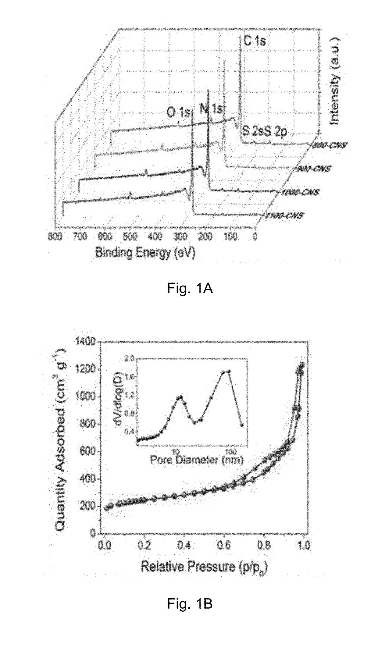
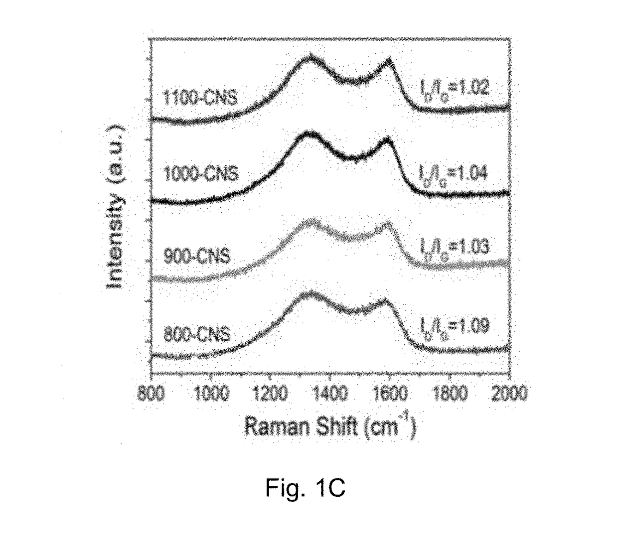
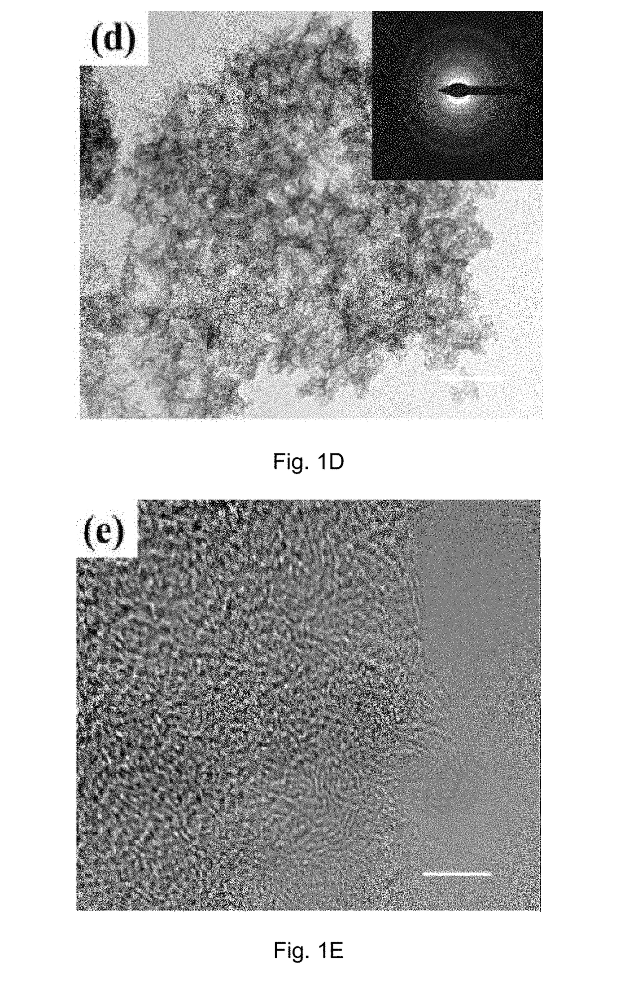
[0083]Physicochemical Characterization of the Carbon Material Prepared in Example 1A

[0084]The crystal structure of the catalyst was identified by a Bruker D2 Phaser X-ray diffractometer with Cu Kα radiation (λ=0.15418 nm) operating at 30 kV and 10 mA, respectively. Raman scattering measurements were performed with a multichannel modular triple Raman system (Renishaw Co.) with confocal microscopy at room temperature using the 633 nm laser. The morphology and microstructure of the samples were revealed by a JEOL-2001F field-emission TEM, and the accessory EELS was used to determine to composite elements. XPS analyses were conducted on an ESCALAB 250 photoelectron spectroscopy (Thermo Fisher Scienctific) at 1.2×10⁻⁹ mbar using Al Kα X-ray beam (1486.6 eV). The XPS spectra were charge corrected to the adventitious C 1s peak at 284.5 eV. TGA were carried out on a TA #SDT Q600 analyser at 30-800° C. with an O2 flow of 40 mL / min. The nitrogen adsorption and desorption isotherms were charac...

example 1c

[0088]ORR and OER Bi-Functional Performances of the Carbon Material Prepared in Example 1A

[0089]All electrochemical measurements were carried out on a CHI 760D electrochemical workstation integrated with a RRDE-3A rotating ring disk electrode apparatus in a typical 3-eletrode system, in which a glassy carbon electrode (GCE, 3 mm in diameter) loaded with different catalysts was used as working electrode, with a Ag / AgCl (in 3 M KCl) electrode and a Pt mesh as reference and counter electrode, respectively. The recorded potential was converted to a reversible hydrogen electrode (RHE). 0.1 M KOH or 0.1 M HClO4 solution served as the electrolyte for ORR measurements. The loading masses for metal-free catalysts were 140 μg cm−2 for alkaline solution and 600 μg cm−2 for acidic electrolyte. Pt / C (Alfa Acesar, 20 wt.-%) with a loading mass of 140 μg cm−2 was used for reference. All the ORR currents presented in the figures are Faradaic currents, i.e., after correction for the capacitive curre...


PUM


Abstract

A method for preparing a hierarchically porous doped carbon material includes the steps of heating a mixture including an etching agent precursor and a pore-generating agent. The pore-generating agent is embedded in a matrix including a carbon source and a dopant source for simultaneously carbonizing the carbon source. The method further includes doping with the dopant and etching the pore-generating agent for obtaining the hierarchically porous doped carbon material.The hierarchically porous doped carbon material can form an electrode, and an energy storage device such as a supercapacitor can include such an electrode. The hierarchically porous doped carbon material can also help form an energy storage and conversion device such as a metal-air battery or a regenerative fuel cell.

Description

TECHNICAL FIELD[0001]The present invention relates to a method for preparing a hierarchically porous doped carbon material, especially preferably but not exclusively a hierarchically porous N, S dually-doped carbon material. Said method comprises a simultaneous carbonizing of a carbon source, doping with a dopant and etching of a pore-generating agent in one reaction step for obtaining the hierarchically porous doped carbon material. The present invention further provides the hierarchically porous doped carbon material obtainable by, in particular obtained by said method. In still another aspect, the present invention provides an electrode comprising said hierarchically porous doped carbon material and an energy storage device such as a supercapacitor comprising said electrode. Additionally, the present invention provides an energy storage and conversion device comprising said hierarchically porous doped carbon material such as a metal-air battery or a regenerative fuel cell.BACKGRO...

Claims


Application Information

Patent Timeline
IPC IPC(8): H01M4/96H01M12/06H01M8/18H01M4/86H01M4/88
CPCH01M4/96H01M12/06H01M8/18H01M4/8878H01M4/8652H01M4/8875H01M4/8605Y02E60/50
Inventor ZHI, CHUNYIPEI, ZENGXIA
Owner CITY UNIVERSITY OF HONG KONG
Why Eureka
Try Eureka