Process for producing compressed hydrogen in a membrane reactor and reactor therefor

a membrane reactor and hydrogen compression technology, applied in separation processes, chemical/physical/physical-chemical processes, energy-based chemical/physical/physical-chemical processes, etc., can solve the problems of high hydrogen recovery, significant partial pressure difference of hsub>2, and complex overall process, and achieve the effect of low conversion

Active Publication Date: 2019-09-19
COORSTEK MEMBRANE SCI AS
View PDF0 Cites 7 Cited by
  • Summary
  • Abstract
  • Description
  • Claims
  • Application Information

AI Technical Summary

Benefits of technology

[0070]When the process of the invention involves such a reforming reaction, lower conversion is acceptable, especially with respect to methane. Conversions of at least 95 wt %, preferably at least 97 wt %, e.g. 99 wt % or more are possible. This means that almost all the substance (typically an alkane) fed to the reactor is converted. The protonic membrane removes hydrogen from the reaction zone and facilitates a near 100% conversion at temperature as low as 800° C.
[0071]The overall reforming reaction (steam reforming+water-gas-shift) is endothermic, and conventionally heat can be supplied by heat transfer through the membrane from the exothermic reaction between permeated hydrogen and sweep air. In the present invention, heat is preferably supplied via ohmic losses and hence joule energy as discussed further below. We do not need to react the desired hydrogen with oxygen to generate heat for the reforming reaction. The membrane enables heat management within the system.
[0072]Further, compared to using complex metal membranes or unstable perovskites of the prior art, the proton conducting membrane of this invention is stable even in chemically harsh conditions at high temperatures.

Problems solved by technology

The drawback for the Pd-SMR is the significant partial pressure difference of H2 needed across the membrane, pH2(retanate)>pH2(permeate).
When the hydrogen partial pressure in the retanate is low, high hydrogen recovery will be challenging.
This is demanding and adds complexity to the overall process and inhibits high energy efficiencies.
However, by using an oxygen containing sweep, a portion of the permeated hydrogen will be consumed in the reaction with oxygen and thereby decrease the hydrogen recovery.
Further, although a counter flow reactor configuration can be used, the hydrogen recovery will be limited by the partial pressure of hydrogen content in the sweep gas.
1) Additional separation step of hydrogen from steam is needed and
2) partial pressure of hydrogen cannot exceed that of partial pressure on feed side.
Several chemical processes are thermodynamically limited and / or endothermic and can only be operated at low conversion at low / medium temperatures.
This restricts the system efficiencies, both on a carbon and energy basis.
Herein, with hydrogen being a part of the reaction product, the yield of the desired product is thermodynamically limited by the partial pressure of hydrogen in the product mixture.
This also restricts the system efficiencies, on energy basis.
The production of external heat lowers the total energy efficiency of the system.
It is generally accepted that the hydrogen compressor technology will not be able to meet future infrastructure demands in a cost-effective manner Currently, the hydrogen compressors used today face considerable wear due to the usage of technology with moving parts.
Research has shown that for piston pumps the piston sealing ring fails due to non-uniform pressure distribution, and failure of pistons is due to severe impact.
Diaphragm compressors are prone to shorter lifetimes due to contaminations / debris in the H2 gas and improper priming procedures when restarting a compressor after stopping.
The operating pressures is high enough to cause local plastic deformation around trapped hard particles leaving residual stresses that reduce the fatigue life of the diaphragm.
There remain challenges in designing these electrochemical compressors, such as their energy efficiencies.

Method used


Image

  • Process for producing compressed hydrogen in a membrane reactor and reactor therefor
  • Process for producing compressed hydrogen in a membrane reactor and reactor therefor
  • Process for producing compressed hydrogen in a membrane reactor and reactor therefor

Examples


example 1

Membrane Preparation

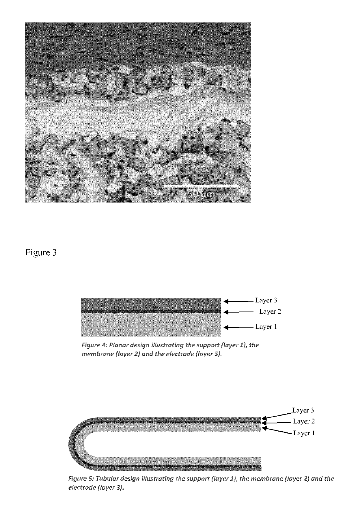
[0278]A tubular asymmetric membrane of 60 wt. % Ni—BaZr0.7Ce0.2Y0.1O3-y (BZCY72) support with a 30 μm dense membrane was synthesized using a reactive sintering approach (Coors et al. Journal of Membrane Science 376 (2011) 50-55). Precursors of BaSO4, ZrO2, Y2O3 and CeO2 were mixed in stoichiometric amounts (metal basis) together in a Nalgene bottle on ajar roller for 24 h. The material was dried in air and sieved through a 40 mesh screen. This forms a precursor mixture.

[0279]Two portions of the mix were mixed additionally with 64 wt. % NiO. One of those portions was then blended with water soluble acrylic and cellulosic ether plasticizer to prepare the extrusion batch.

[0280]Green tubes were extruded using a Loomis extruder. The extruded tubes were then dried and spray coated with the precursor mixture after drying. After a second drying step the tubes were dip coated in a solution of the previous second portion (containing NiO). The tubes were co-fired by hang-fi...

example 2

Membrane Preparation

[0284]2 tubular membranes, A and B, of 6 cm each where prepared as described in Example 1. Both segments have outer electrode areas of 14.1 cm2. Segment A is connected with segment B in series. The two segments are connected in series together using a glass ceramic based interconnect. Segment A is further sealed to an alumina riser of 25 cm length using a glass ceramic seal. Segment B is capped with a glass ceramic seal.

Catalyst

[0285]The anode support structure consisting of the 60 wt. % Ni—BZCY72 provides sufficient catalytic activity

Reactor and Setup

[0286]The reactor consists of a 1″ metallic outer tube (800 HT). The segmented ceramic tube on riser was mounted with Swagelok fittings seal and placed inside the outer tube. Inner gas tube and current collector consisted of at Ni-tube (O.D. 4.6 mm). To ensure contact with the support, Ni wool was put into segment A. The temperature was monitored with 3 thermocouples, two outside the reactor at heights corresponding...


PUM

PropertyMeasurementUnit
temperatureaaaaaaaaaa
pressureaaaaaaaaaa
electric fieldaaaaaaaaaa

Abstract

A process for direct compression of hydrogen separated from a hydrocarbon source is described herein. The process comprises a first zone wherein a hydrocarbon reaction that produce hydrogen occurs, a ceramic proton conductor which under an applied electric field transport hydrogen from said first zone to said second zone, and a second zone where compressed hydrogen is produced. The heat energy generated by ohmic resistance in the membrane is partially recuperated as chemical energy in the hydrocarbon reforming process to generate hydrogen.

Description

[0001]This invention relates to a process for obtaining and compressing hydrogen from a hydrocarbon source. In particular, the invention uses a hydrogen transport membrane to separate hydrogen from its source and create hydrogen pressure on the permeate side of the membrane. An electric field is applied to the membrane to encourage proton transport and Joule heating during the application of the electric field can be used to supply heat for a dehydrogenation process, e.g. steam reforming of methane.BACKGROUND[0002]Hydrogen can be produced from steam methane reforming (SMR), following the equation:CH4+H2O↔3H2+CO.[0003]The reaction is endothermic (ΔH298=206 kJ mol−1), and is commercially operated at high temperatures, >900° C. Downstream the hydrogen concentration is further increased by the shift reaction:CO+H2O↔H2+CO2(ΔH298=−41 kJ mol−1),[0004]before the hydrogen is separated using e.g. pressure swing absorption (PSA). Finally, the hydrogen is compressed using available compresso...

Claims


Application Information

Patent Timeline
Patent Type & Authority Applications(United States)
IPC IPC(8): C01B3/50C01B3/34C01B32/40C01B32/50C01B3/26B01D71/02B01D53/32B01J19/24B01J19/08
CPCC01B2203/041B01J19/087C01B2203/0233C01B2203/0277C01B2203/1241C01B2203/047B01J2219/0892C01B2203/085B01D2259/812C01B3/34B01D71/024B01J19/2475C01B3/503C01B32/40B01J2219/0803C01B3/26C01B2203/0475B01J2219/0875B01D53/326C01B32/50B01J19/248B01J19/2485B01J8/009C25B1/02C25B9/05C25B9/23C25B11/077C25B13/07C25B11/054C25B11/067B01D2256/16C01B3/50C25B13/04C25B11/0773B01D71/0271
Inventor KJØLSETH, CHRISTIANMALERØD-FJELD, HARALDVESTRE, PER KRISTIAN
Owner COORSTEK MEMBRANE SCI AS
Why Eureka
Try Eureka