
Method of improving the charge/discharge cycle life and safety of an alkali metal-sulfur secondary battery

a technology of alkali metalsulfur and secondary batteries, which is applied in the direction of cell components, final product manufacturing, sustainable manufacturing/processing, etc., can solve the problems of dendrite formation and related internal shorting, limited success, and various carbon-sulfur composites used for this purpose, so as to reduce internal resistance and improve contact

Pending Publication Date: 2020-07-09
GLOBAL GRAPHENE GRP INC
View PDF2 Cites 2 Cited by
  • Summary
  • Abstract
  • Description
  • Claims
  • Application Information

AI Technical Summary

Benefits of technology

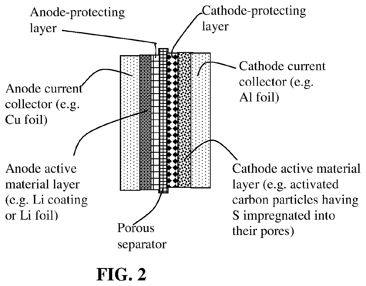
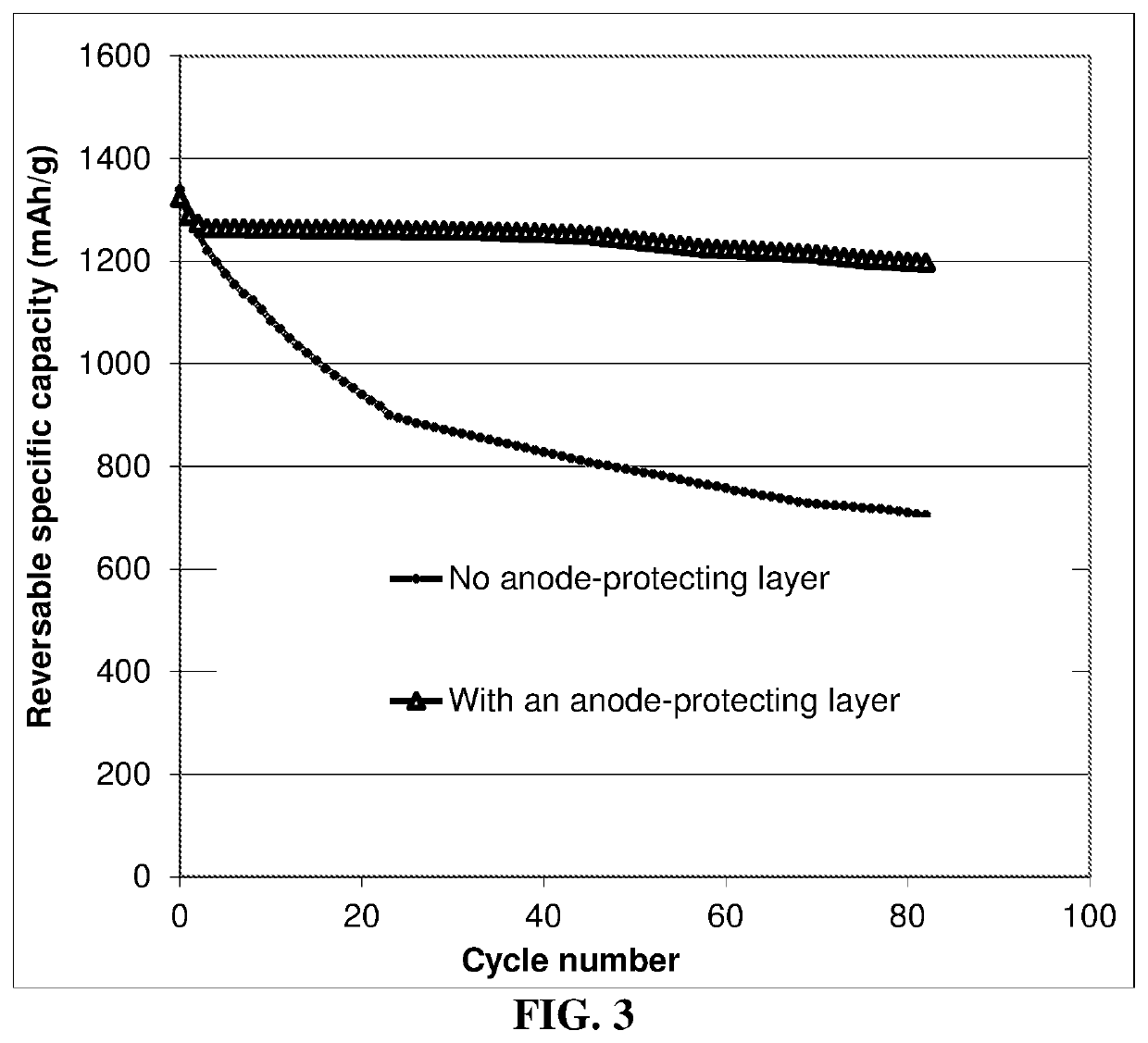
The invention provides a method to improve the life of a rechargeable battery made with an alkali metal-sulfur cell. This method involves the use of an electronically non-conducting anode-protecting layer between the anode and cathode layers. This layer helps to prevent the growth of dendrites (metal filaments) that can cause damage to the battery and to improve the stability of the battery's interface with the electrolyte. The anode-protecting layer is made of an elastomer with high tensile elastic strain, high conductivity for lithium or sodium ions, and low conductivity for electrons. The use of this layer results in a battery with high sulfur content, high sulfur utilization efficiency, high energy density, no dendrite or dead lithium or sodium issue, and a long cycle life.

Problems solved by technology

However, the current Li-sulfur cells reported by industry leaders in sulfur cathode technology have a maximum cell specific energy of 250-400 Wh / kg (based on the total cell weight), which is far below what is possible.
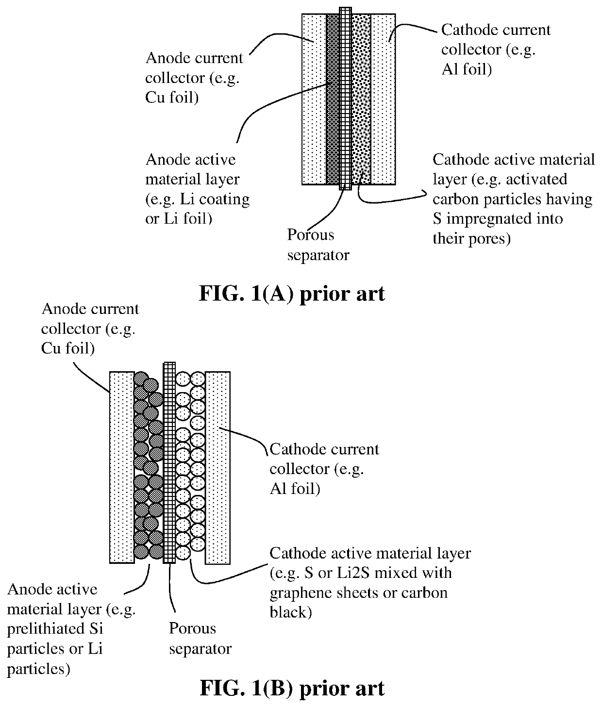
In summary, despite its considerable advantages, the Li—S cell is plagued with several major technical problems that have thus far hindered its widespread commercialization:(1) Conventional lithium metal cells still have dendrite formation and related internal shorting issues.(2) Sulfur or sulfur-containing organic compounds are highly insulating, both electrically and ionically.
Various carbon-sulfur composites have been utilized for this purpose, but only with limited success owing to the limited scale of the contact area.
This is mainly due to the high solubility of the lithium polysulfide anions formed as reaction intermediates during both discharge and charge processes in the polar organic solvents used in electrolytes.
In addition, the solid product that precipitates on the surface of the positive electrode during discharge becomes electrochemically irreversible, which also contributes to active mass loss.(4) More generally speaking, a significant drawback with cells containing cathodes comprising elemental sulfur, organosulfur and carbon-sulfur materials relates to the dissolution and excessive out-diffusion of soluble sulfides, polysulfides, organo-sulfides, carbon-sulfides and / or carbon-polysulfides (hereinafter referred to as anionic reduction products) from the cathode into the rest of the cell.
This process leads to several problems: high self-discharge rates, loss of cathode capacity, corrosion of current collectors and electrical leads leading to loss of electrical contact to active cell components, fouling of the anode surface giving rise to malfunction of the anode, and clogging of the pores in the cell membrane separator which leads to loss of ion transport and large increases in internal resistance in the cell.
Some interesting cathode developments have been reported recently to contain lithium polysulfides; but, their performance still fall short of what is required for practical applications.
Sodium metal (Na) and potassium metal (K) have similar chemical characteristics to Li and the sulfur cathode in room temperature sodium-sulfur cells (RT Na—S batteries) or potassium-sulfur cells (K—S) face the same issues observed in Li—S batteries, such as: (i) low active material utilization rate, (ii) poor cycle life, and (iii) low Coulombic efficiency.
Again, these drawbacks arise mainly from insulating nature of S, dissolution of S and Na or K polysulfide intermediates in liquid electrolytes (and related Shuttle effect), and large volume change during charge / discharge.
It may be noted that in most of the open literature reports (scientific papers) and patent documents, scientists or inventors choose to express the cathode specific capacity based on the sulfur or lithium polysulfide weight alone (not the total cathode composite weight), but unfortunately a large proportion of non-active materials (those not capable of storing lithium, such as conductive additive and binder) is typically used in their Li—S cells.

Method used


Image

  • Method of improving the charge/discharge cycle life and safety of an alkali metal-sulfur secondary battery
  • Method of improving the charge/discharge cycle life and safety of an alkali metal-sulfur secondary battery
  • Method of improving the charge/discharge cycle life and safety of an alkali metal-sulfur secondary battery

Examples


example 1

Sulfur with Carbon / Graphite Particles Via Ball-Milling to Form Sulfur-Containing Particles

[0119]Sulfur and lithium polysulfide particles and particles of soft carbon (i.e. graphitizable disordered carbon), natural graphite, mesophase carbon, expanded graphite flakes, carbon nanofibers, and graphene sheets (50% to 85% by weight of S in the resulting composite or hybrid) were physically blended and then subjected to ball milling for 2-24 hours to obtain S-containing composite particles (typically in a ball or potato shape). The particles have a typical size of 1-10 μm. These particles, along with a conductive additive (5% by wt.) and a resin binder (PVDF, 5%), were then combined and made into a layer of cathode using the well-known slurry coating procedure.

example 2

lfur Melt or Liquid Solution Mixing

[0120]One way to combine sulfur with a conducting material (e.g. carbon / graphite particles) is to use a solution or melt mixing process. Highly porous activated carbon particles, chemically etched mesocarbon microballs (activated MCMBs), and exfoliated graphite worms were mixed with sulfur melt at 117-120° C. (slightly above the melting point of S, 115.2° C.) for 10-60 minutes to obtain sulfur-impregnated carbon particles for use a cathode active material.

example 3

on of Sulfur-Coated Graphene Sheets and their Secondary Particles (Particulates)

[0121]The step involves producing vapor of elemental sulfur, allowing deposition of S vapor on surfaces of single-layer or few-layer graphene sheets. The graphene sheets, suspended in a liquid medium (e.g. graphene oxide in water or graphene in NMP), were sprayed onto a substrate (e.g. glass surface) to form a thin layer of graphene sheets. This thin layer of graphene was then exposed to sublimation-generated physical vapor deposition. Sublimation of solid sulfur occurs at a temperature greater than 40° C., but a significant and practically useful sublimation rate typically does not occur until the temperature is above 100° C. We typically used 117-160° C. with a vapor deposition time of 10-120 minutes to deposit a thin film of sulfur on graphene surface (sulfur thickness being approximately from 1 nm to 10 nm). This thin layer of graphene having a thin film of sulfur deposited thereon was then easily br...


PUM


Abstract

Provided is a method of improving a cycle-life of a rechargeable alkali metal-sulfur cell, the method comprising implementing an electronically non-conducting anode-protecting layer between an anode active material layer and a cathode active material without using a porous separator in the cell, wherein the anode-protecting layer has a thickness from 1 nm to 100 μm and comprises an elastomer having a fully recoverable tensile elastic strain from 2% to 1,000%, a lithium ion or sodium ion conductivity from 10−8 S / cm to 5×10⁻² S / cm, and an electronic conductivity less than 10−4 S / cm when measured at room temperature. This battery exhibits an excellent combination of high sulfur content, high sulfur utilization efficiency, high energy density, no known dendrite issue, no dead lithium or dead sodium issue, and a long cycle life.

Description

FIELD OF THE INVENTION[0001]The present invention provides a protective layer for use in a secondary or rechargeable alkali metal-sulfur battery, including the lithium-sulfur battery, sodium-sulfur battery, and potassium-sulfur battery.BACKGROUND[0002]Rechargeable lithium-ion (Li-ion) and lithium metal batteries (including Li-sulfur and Li metal-air batteries) are considered promising power sources for electric vehicle (EV), hybrid electric vehicle (HEV), and portable electronic devices, such as lap-top computers and mobile phones. Lithium as a metal element has the highest capacity (3,861 mAh / g) compared to any other metal or metal-intercalated compound as an anode active material (except Li4.4Si, which has a specific capacity of 4,200 mAh / g). Hence, in general, Li metal batteries have a significantly higher energy density than lithium ion batteries.[0003]One of the most promising energy storage devices is the lithium-sulfur (Li—S) cell since the theoretical capacity of Li is 3,861...

Claims


Application Information

Patent Timeline
IPC IPC(8): H01M10/04H01M10/0525H01M4/58H01M4/36H01M4/38H01M4/24H01M50/414H01M50/434H01M50/437H01M50/489H01M50/494H01M50/497
CPCH01M2010/4292H01M10/0525H01M4/364H01M4/5815H01M4/382H01M10/044H01M4/24H01M4/366Y02E60/10H01M4/622H01M4/623H01M4/624H01M4/625H01M2300/0082H01M2300/0068H01M10/052H01M4/38H01M10/054H01M10/056H01M4/381H01M50/44H01M50/446Y02P70/50H01M50/437H01M50/414H01M50/434H01M50/489H01M50/494H01M50/497
Inventor JANG, BOR Z.
Owner GLOBAL GRAPHENE GRP INC
Learn More