
Electrocatalyst powders, methods for producing powders and devices fabricated from same

a technology of electrocatalyst powder and powder, which is applied in the direction of metal/metal-oxide/metal-hydroxide catalyst, fixed capacitor, lithium compound, etc., can solve the problems of low power of zinc-air batteries, limited total power, and poor rechargeability/cycle li

Inactive Publication Date: 2003-12-09
CABOT CORP
View PDF54 Cites 212 Cited by
  • Summary
  • Abstract
  • Description
  • Claims
  • Application Information

AI Technical Summary

Benefits of technology

It is an advantage of the present invention that the composition of the electrocatalyst particles can be homogeneous. A degree of homogeneity in materials is often not obtainable by traditional forming methods such as liquid precipitation. However, it is also possible to intentionally provide compositional gradients within the electrocatalyst particles. For example, the active species concentration in a composite particle can be higher or lower at the surface of the support phase than near the center and gradients corresponding to compositional changes of 10 to 100 weight percent can be obtained. When the particles are deposited by direct-write deposition, the particles retain their structural morphology and therefore the functionality of the compositional gradient can be exploited.
that the composition of the electrocatalyst particles can be homogeneous. A degree of homogeneity in materials is often not obtainable by traditional forming methods such as liquid precipitation. However, it is also possible to intentionally provide compositional gradients within the electrocatalyst particles. For example, the active species concentration in a composite particle can be higher or lower at the surface of the support phase than near the center and gradients corresponding to compositional changes of 10 to 100 weight percent can be obtained. When the particles are deposited by direct-write deposition, the particles retain their structural morphology and therefore the functionality of the compositional gradient can be exploited.
The preferred form of carbon for crystalline supported active species are those which are amorphous. The preferred carbons for supported metals like Pt are carbons that are crystalline since Pt dispersion is favored by reduced carbon surfaces with substantially no surface hydroxyls. For supported MnO.sub.x, it is also preferred to have a crystalline carbon support. Preferably, the crystallinity of the primary particles constituting the support phase is controlled through the selection of materials chosen for a specific application. Graphitic carbon is preferred for long term operational stability of fuel cells and batteries. Amorphous carbon is preferred when a smaller crystallite size is desired for the supported active species.
The overall density of the secondary support phase in the composite particles is related to the porosity of the support phase. It is preferred that the accessible (e.g., open) porosity in the composite electrocatalyst particles is from about 5 to 98 percent and more preferably is at least about 40 percent. The pore size distribution in the secondary support phase can also be controlled and the average pore size is preferably from about 10 to about 100 nanometers. High porosity is advantageous for rapid transport of species into and out of the secondary structures. Lower particle densities also allow easier suspension of the particles for printing techniques such as ink-jet deposition where suspension of particles for long periods is required. As an example, an aerogel carbon or metal oxide can have a density much lower than 1 g / cm.sup.3.
Agglomeration of the electrocatalyst particles can affect the properties of the powder batch such as the ability to disperse the powder into liquids used to deposit the particles. It is therefore preferred that minimal agglomeration of the particles exist in the powder batch.
It is also an advantage of the present invention that the electrocatalyst particles are substantially spherical in shape. That is, the particles are preferably not jagged or irregular in shape. Spherical particles can advantageously be deposited using a variety of techniques, including direct write deposition, and can form layers that are thin and have a high packing density.

Problems solved by technology

The two major problems associated with secondary zinc-air batteries, however, are limited total power and poor rechargeability / cycle lifetime.
The main reason for the low power of zinc-air batteries is believed to be related to the inefficiency of the catalytic reaction to reduce oxygen in the air electrodes.
Poor accessibility of the catalyst and the local microstructural environment around the catalyst and adjoining carbon reduces the efficiency of the oxygen reduction.
Rechargeability is also a problem with zinc-air batteries.
Specifically, it is believed that corrosion of the carbon used for the electrocatalyst in these systems leads to a loss in capacity and hence, a decreased discharge time.
A significant obstacle to the wide-scale commercialization of such devices is the need for highly efficient electrocatalyst materials for this conversion process.
The critical issues that must be addressed for the successful commercialization of fuel cells are cell cost, cell performance and operating lifetime.
Platinum metal is very expensive and a significant cost reduction in the electrocatalyst is necessary for these cells to become economically viable.
However, reducing the amount of precious metal is not a suitable solution because there is also a strong demand for improved cell performance which relies on the presence of the platinum electrocatalyst.
The major technical challenge is improving the performance of the cathode with air as the oxidant.
The foregoing method generally results in poor control over the composition and microstructure of the composite powders.
The inability to control the fundamental electrocatalyst powder characteristics is a major obstacle for the future development of energy storage and production devices.
The foregoing methods generally result in poor control over the composition and microstructure of the electrocatalytic materials, as well as poor control over the dispersibility and surface area of the active species on the carbon surface.
Further, alloy compositions such as platinum / ruthenium used for oxygen reduction in a fuel cell are not made in a consistently reproducible fashion.
The inability to control the fundamental powder characteristics is a major obstacle to the development of more efficient electrocatalyst materials.
A degree of homogeneity in materials is often not obtainable by traditional forming methods such as liquid precipitation.
It is believed that higher oxidation states are detrimental to electrocatalyst powder activity.
The use of a liquid organic carbon precursor typically results in amorphous carbon, which is not desirable for most electrocatalyst applications.
Nanometer-sized particles are difficult to produce in the presence of other particles while maintaining control of their dispersion on a support surface.
Excess surfactants, particularly high molecular weight surfactants, can remain on the electrocatalyst particle surface and degrade the catalytic activity if not fully removed.
For example, some precursor compositions cannot be economically atomized by ultrasonic methods.
However a threshold gas flow rate exists beyond which the droplet removal rate reaches an asymptotic value or declines due to distortions in the fountain caused by the higher velocity gas.
These droplets lose water quickly and cause the bulk fluid to concentrate over time.
More complex solutions may require monitoring of the pH and the addition of other components such as acids or bases.
However, ultrasonic fountains typically generate fewer droplets per unit time per device and are less efficient in terms of energy conversion than other systems.
However, lower frequencies produce larger particles than higher frequencies such that the ultrasonic nozzle is unsuitable for applications requiring a small particle size.
However, highly turbulent systems may give rise to undesirable particle deposition and losses.
The disadvantages of the hot-wall reactor include limited scalability due to thermal transport properties and equipment costs.
However, scale-up of modified systems can be cost prohibitive.
Equipment downstream of the spray dryer can also impose temperature limitations on the outlet temperature of the system that will also limit the maximum conversion temperature.
The lower operating temperature of a spray dryer limits the ability to achieve the chemical reactions during spray conversion.
In the present spray process, the temperature can be significantly higher, but if carbon is included as one of the phases, there is an upper temperature limit where the carbon will oxidize if an oxidizing environment such as air is used.
Further, the accumulation of liquid at sharp edges can result in re-release of undesirably large droplets back into the aerosol 108, which can cause contamination of the particulate product 116 with undesirably large particles.
Also, over time, such liquid collection at sharp surfaces can cause fouling of process equipment, impairing process performance.
Disadvantages of using a metallic tube include limited operating temperature and increased reactivity in some reaction systems.
One disadvantage of using the separator 126, however, is that the rate of droplet production from the atomization cones 162 is reduced, often by a factor of two or more, relative to designs in which the liquid feed 102 is in direct contact with the ultrasonic transducer discs 102.
If the temperature becomes too high, however, it can have a detrimental effect on droplet loading in the aerosol 108.
Because of the relative complexity of operating in that mode, however, it is not preferred.
However, such batteries have a low power primarily due to the inefficiency of the catalytic reactions at the air electrode 502.
The thinner layers result in reduced mass and volume and therefore an increase in the volumetric and gravimetric energy density of the battery.
This is the case in metal-air batteries where the transport of O.sub.2 or hydroxide ion in the air electrode can be rate limiting.
Shorter diffusional distances and lower diffusional barriers will lead to a higher rate of drain for this type of device.
Depending upon the density of the particle compound, however, particles with a high density relative to the liquid in which they are dispersed and with a size in excess of about 0.5 .mu.m cannot be suspended in a liquid that has a sufficiently low viscosity to be deposited using a direct-write tool, particularly an ink-jet device.
However, such devices have primarily been used to deposit inks of soluble dyes.
However, some filtration of suspensions may occur if the particles are too large to pass through the channels or onboard filters.

Method used


Image

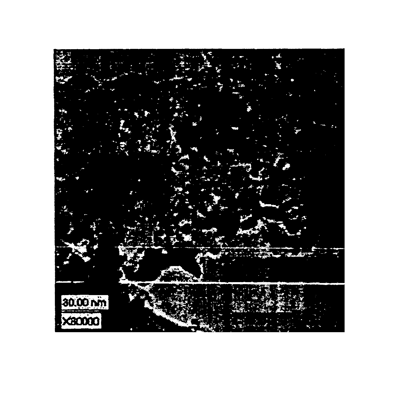
  • Electrocatalyst powders, methods for producing powders and devices fabricated from same
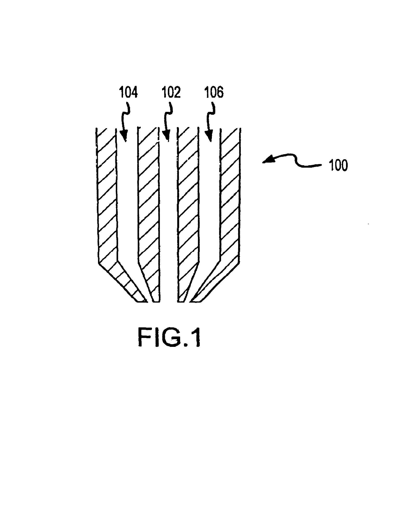
  • Electrocatalyst powders, methods for producing powders and devices fabricated from same
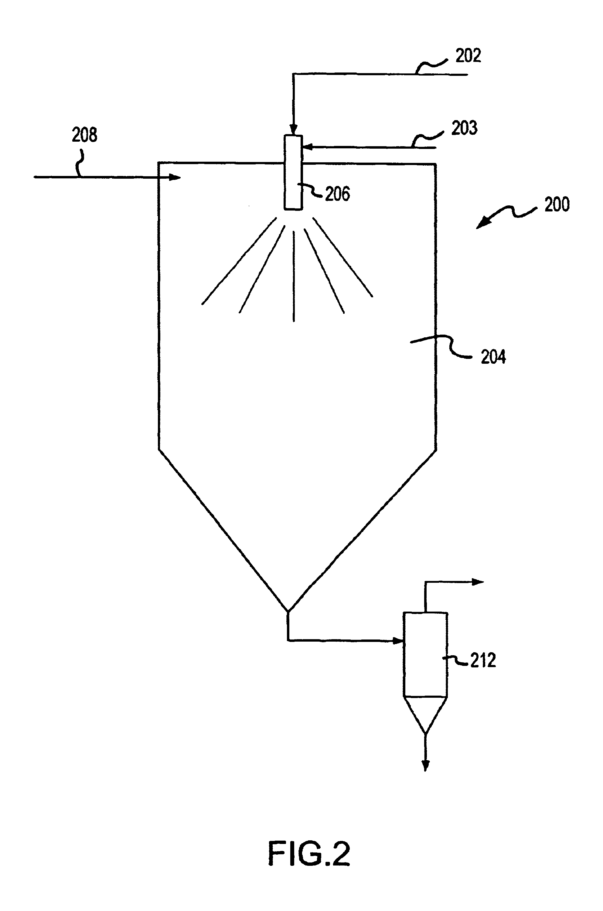
  • Electrocatalyst powders, methods for producing powders and devices fabricated from same

Examples


examples 41a through 41d

illustrate the influence of variable amounts of surfactant in the spray solution, variation in the weight percent of Mn as well as the spray conversion temperature as compared to Examples 30A and 30C. A comparison between Examples 30C and 41A leads to the conclusion that a higher conversion temperature is not necessarily beneficial for the catalyst morphology and performance. Both the MnO.sub.x dispersion and the electrocatalytic activity are lower for Example 41A, which was made at a higher conversion temperature with all other parameters being kept constant.

It appears that the lower the amount of added surfactant, the better the dispersity and electrocatalytic performance (compare Example 41A to Example 41B). Doubling the Mn concentration does not lead to any improvement in the electrocatalytic performance. In contrast, it is the lowest in the series of spray nozzle generated samples. This result indicates that the surface coverage at 10 weight percent Mn and about 25 m.sup.2 / g s...

example 44e

prepared with spray nozzle generation has identically high performance to the ultrasonically generated Example 23A. prepared at the lowest conversion temperature of 149.degree. C., with minimal addition of surfactant, 10 weight percent Mn and 5 weight percent solution concentration. Most likely these particular conditions (along with others such as residence time) ensure good kinetic conditions for the formation and distribution of the MnO.sub.x active species on the carbon support.

A higher surface area carbon support compared to the carbon support used for the previous spray conversion examples (surface area of 254 m.sup.2 / g) will provide higher support surface area available for the MnO.sub.x absorption. The surface area reduction after the spray conversion observed for the previous carbon support was on the order of about 10 times. Because of that reduction of the surface area, higher loading of MnO.sub.x was not beneficial for the electrocatalytic activity because of the lack o...


PUM

PropertyMeasurementUnit
cluster sizeaaaaaaaaaa

Abstract

Electrocatalyst powders and methods for producing electrocatalyst powders, such as carbon composite electrocatalyst powders. The powders have a well-controlled microstructure and morphology. The method includes forming the particles from an aerosol of precursors by heating the aerosol to a relatively low temperature, such as not greater than about 400° C.

Description

1. FIELD OF THE INVENTIONThe present invention relates to particulate materials such as electrocatalyst powders for the fabrication of energy devices and to methods for producing such powders, as well as products and devices incorporating the powders. The powders are preferably produced by spray conversion of precursors to the particulate materials.2. DESCRIPTION OF RELATED ARTWith the advent of portable and hand-held electronic devices and an increasing demand for electric automobiles due to the increased strain on non-renewable natural resources, there is a need for the rapid development of high performance, economical power systems. Such power systems require improved devices for energy storage using batteries and energy generation using fuel cells.Batteries can be divided into primary (non-rechargeable) and secondary (rechargeable) batteries. Common types of primary batteries include metal-air batteries such as Zn-air, Li-air and Al-air, alkaline batteries and lithium batteries....

Claims


Application Information

Patent Timeline
Patent Type & Authority Patents(United States)
IPC IPC(8): B01J2/00B01J19/24B01J2/16B01J19/10B01J2/02B01J2/04B01J2/18B01J19/00B01J13/02B22F1/02B22F9/24B22F1/00B22F9/02B22F9/16B24B37/04C01G23/00C01B17/20C01B17/00C01G25/00C01G15/00C01B13/18C09K11/59C09K11/67C09K11/02C09K11/08C09K11/77C09K11/62C09K3/14C09K11/56C22C29/00C22C32/00C22C1/10C09G1/00C09G1/02H01L23/498H01L23/48H01J29/20H01L21/02H01L21/321H05K1/09B22F1/054B22F1/18H01G4/008
CPCB01J2/003B01J2/006B01J2/02B01J2/04B01J13/02B01J19/10B01J19/2405B22F1/0018B22F1/02B22F1/025B22F9/02B22F9/026B22F9/24B24B37/044B82Y30/00C01B13/18C01B13/185C01B17/20C01G15/006C01G23/003C01G23/006C01G25/00C09G1/02C09K3/1436C09K3/1463C09K11/025C09K11/0805C09K11/0877C09K11/562C09K11/565C09K11/567C09K11/595C09K11/625C09K11/671C09K11/7718C09K11/7731C09K11/7734C09K11/7746C09K11/7771C09K11/7774C09K11/7789C09K11/7797C22C1/1026C22C29/00C22C32/0084C22C32/0089H01G4/0085H01J29/20H01L23/49883B01J2219/00112B01J2219/00155B01J2219/00159B01J2219/00162B01J2219/00166B01J2219/00171B01J2219/00186B22F2998/00B22F2999/00C01P2002/60C01P2002/70C01P2004/03C01P2004/32C01P2004/34C01P2004/50C01P2004/52C01P2004/61C01P2004/62C01P2004/80C01P2006/10C01P2006/22C01P2006/60C01P2006/80H01L21/3212H05K1/095H01L2924/0002Y10T428/12896Y10T428/12875Y10T428/12535Y10T428/12181Y10T428/2991Y10T428/1259Y10T428/12625B22F1/0014B22F1/0048B22F3/008B22F2202/11B22F2202/01H01L2924/00Y10T428/31667Y02P10/25B22F1/054B22F1/18B22F10/10B22F1/065B22F1/052
Inventor HAMPDEN-SMITH, MARK J.KODAS, TOIVO T.ATANASSOV, PLAMENATANASSOVA, PAOLINAKUNZE, KLAUSNAPOLITANO, PAULDERICOTTE, DAVID
Owner CABOT CORP
Learn More