Carbonaceous refractory and method for preparing the same

a technology of carbonaceous refractory and refractory material, which is applied in the field of refractory materials, can solve the problems of increasing the damage factor of lining refractory materials, carbonaceous refractory materials having a weak point, and carbonaceous refractory materials, so as to reduce the corrosion rate of refractory materials, reduce the corrosion resistance of pig, and improve the effect of corrosion resistan

Inactive Publication Date: 2005-04-05
NIPPON STEEL CORP +1
View PDF1 Cites 4 Cited by
  • Summary
  • Abstract
  • Description
  • Claims
  • Application Information

AI Technical Summary

Benefits of technology

erably below 10 μm even though the effect of the invention can be materialized when a particle size is less than 35 μm. When the particle size is about 2 μm, satisfactory effect was obtained even when the content of titanium carbide particle is about 5%.
The same effect was obtained when metallic titanium powder, titanium nitride powder or titanium carbonitride (TiCxNy where 0 <x, y<1 and x+y=1) powder was contained, in place of titanium carbide powder. It was found that the same effect was obtained when a mixture of two or three or more of these metallic titanium and these titanium compounds at any ratio is contained at 5 to 20%.
It was found nevertheless that addition of carbides, nitrides or carbonitride of metals conventionally selected from the conventionally used Ti group to known refractory materials in Japanese Patent Laid-open No. Sho-52-141403 for the purpose of forming a protective film of TITANIUM BEAR in the overall inner face of the furnace bottom, and the titanium compound used in Japanese Patent Laid-open No. Sho-53-7709, where titanium bare is formed in the proximity of the surface of a refractory material by adding one or two or more of metals such as Ti and Zr, or alloys, oxides, nitrides or carbides thereof to the raw materials of a carbonaceous refractory material to reduce the corrosion rate of the refractory material, have distinctively deteriorated corrosion resistance against melted pig iron with a low Ti content, or caused significant abrasion due to the flow of melted pig iron. The reason may possibly be as follows. As shown in the analytical results of conventional TiC reagents in FIG. 1, using an X-ray diffraction apparatus RAD-rR (Cu-kα 50 kV/100 mA) manufactured by Rigaku Corporation, an impurity is present in the conventional TiC reagent at 2.7% on the X-ray diffraction peak intensity ratio of the face (220) of Ti3O5 compared to the intensity of the face (111) of TiC. Thus, the oxygen of Ti3O5 reacts with the carbon in the refractory material to form micropores, so that the titanium bare which is supposed to work as a protective layer described in Japanese Patent Laid-open No. Sho-52-141403 is not continuously formed on the entire inner face of the furnace bottom. Hence, a protective layer with a high melting point, which should closely cover the entire surface of the refractory material of the invention, cannot be satisfactorily formed by

Problems solved by technology

Damaging factors toward the lining refractory materials have increased because of the trend of high-pressure operation, Pulverized Coal Injection operation and so on.
Compared with fire clay brick, carbonaceous refractory materials have a weak point because of the dissolution in molten iron.
Currently it is well known that the causes of the damage of carbonaceous refractory materials in blast furnace are carburization dissolution into molten iron, structural destruction due to the penetration of molten iron into the pore, formation of cracks due to the penetration and reaction with alkali and zinc vapors, formation of cracks due to thermal stress and abrasion due to the flow of molten iron.
However, the reduction of a carburization dissolution rate of a carbonaceous refractory material retaining high thermal conductivity and slug resistance is still limited as long as main raw material is carbon aggregate.
Hei-7-172907 is insufficient in view of wettability with molten iron after oxidization at high temperature, because the refractory material does no contain metallic titanium, titanium carbide or titanium ni

Method used


Image

  • Carbonaceous refractory and method for preparing the same
  • Carbonaceous refractory and method for preparing the same
  • Carbonaceous refractory and method for preparing the same

Examples


embodiment 1

ntaining Titanium Carbide

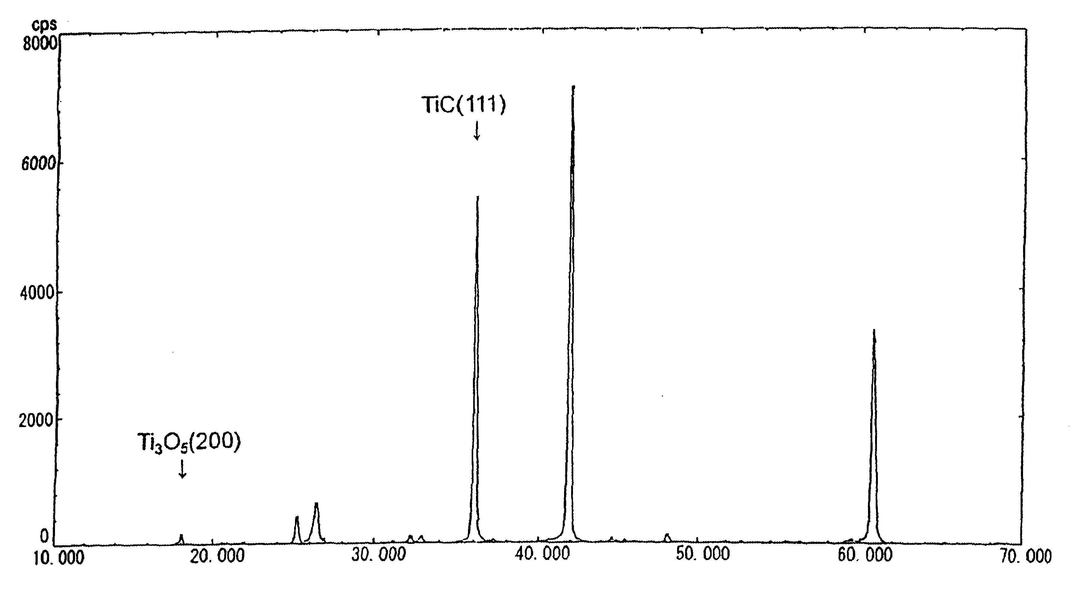
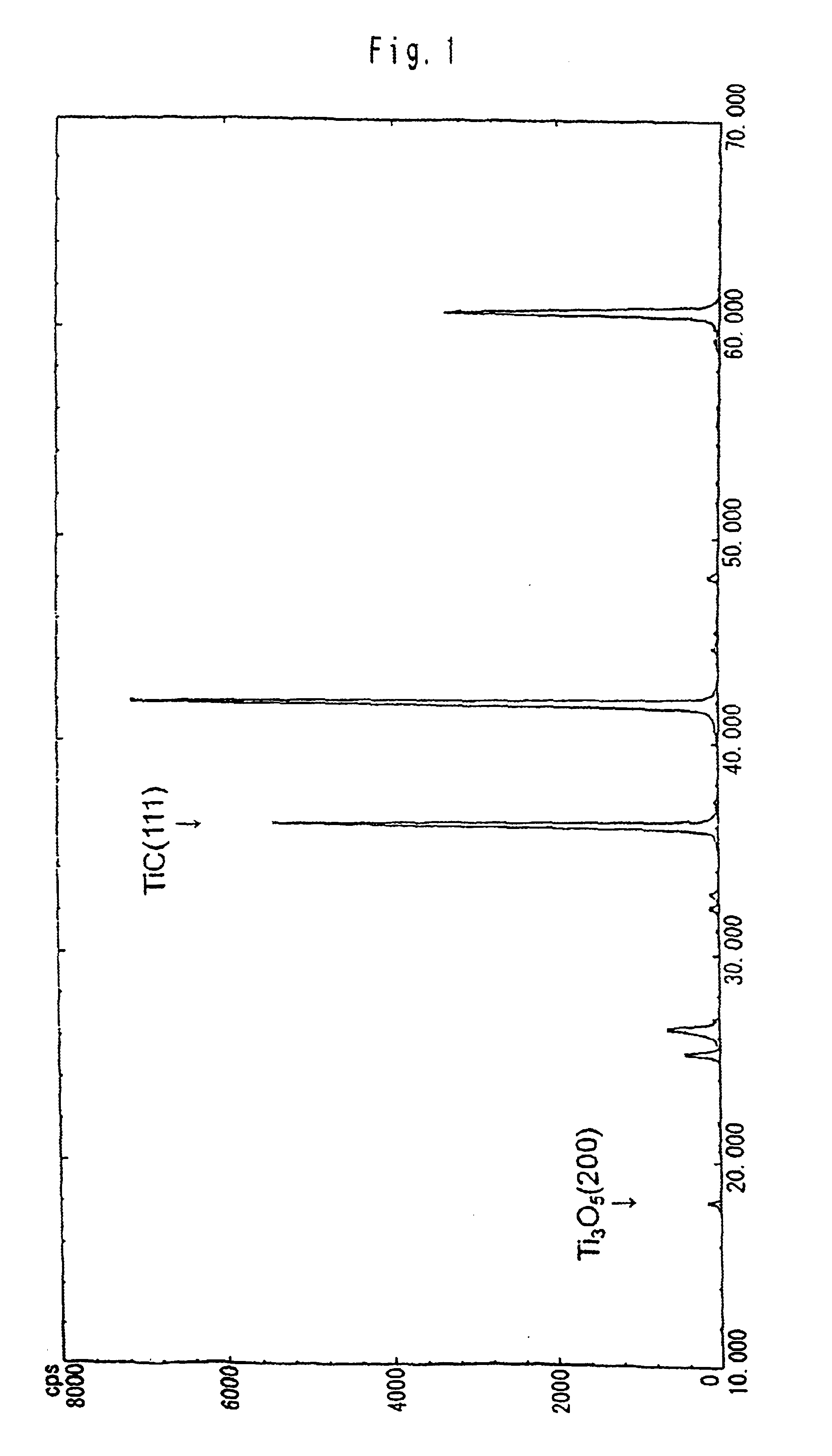
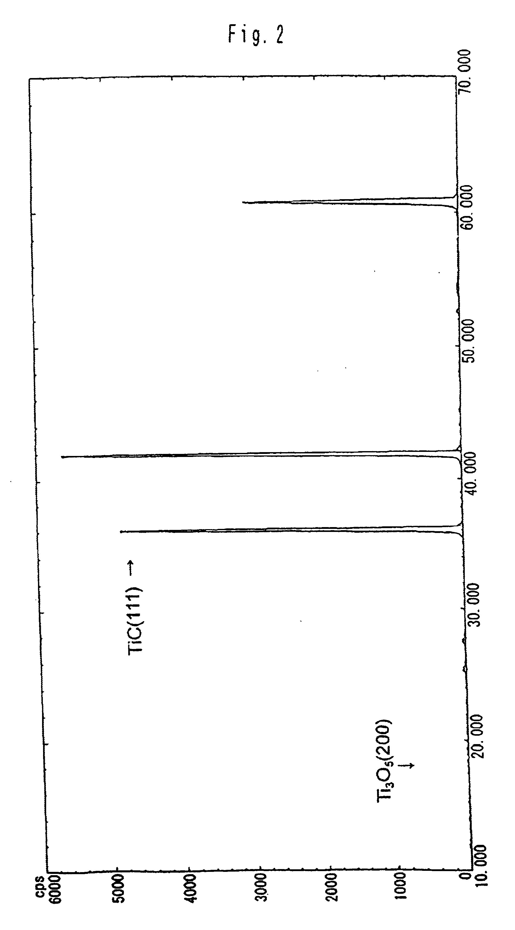
Following the compositions shown in Table 1 and with the procedures described below, carbonaceous refractory materials of Sample 1—1 which contains titanium carbide and Samples 1-2 to 1-5 which do not contain titanium carbide were produced. The applied titanium carbide showed the X-ray diffraction peak intensity ratio as indicated in FIG. 2. The samples were baked in coke breeze. Then, the carbonaceous refractory materials of Sample 1-1 to 1-5 were immersed and rotated in the melt, which was composed of melted pig iron and slug, which floated above the pig iron, from a blast furnace, at 1550° C. for one hour. Thereafter, the samples were recovered, to examine the corrosion ratio at the melted pig iron-immersed portion and at the interface between melted pig iron and slug. Thermal conductivity of the samples was also measured.

Herein, the mold size for forming the carbonaceous refractory materials is of 600×600×2,500 mm, while the sample size for melted pig ir...

embodiment 2

itanium Carbide

Following the compositions shown in Table 2 and by the same procedures as in Embodiment 1, carbonaceous refractory materials of Samples 2-1 to 2-7 were prepared, while the blend ratio of Tic was varied within a range of 0 to 11 parts. The applied titanium carbide showed the X-ray diffraction peak intensity ratio as indicated in FIG. 2. The particle diameter of alumina was 2 to 3 μm, while the particle diameter of metallic silicon was below 74 μm. Herein, the TiC particle diameter is 7 μm, while the mold size for forming the carbonaceous refractory materials is of 100 Φ×130 mm and the sample size is 20Φ×70 mm.

The upper parts of these Samples 2-1 to 2-7 were protected with alumina sleeve, so that only the lower parts of the samples to be corroded. The volume reduction ratio of the lower parts between prior to and after the test was defined as melted pig iron corrosion ratio. Herein, the volume was measured by Hydrostatic Method. As the melted pig iron source, cast iron ...

embodiment 3

anium Compounds

By the same procedures as in Embodiment 1 and at the same blend ratio of Sample 2-7 shown in Table 2, carbonaceous refractory materials were produced, except the kinds of mixed Ti compounds, such as metal titanium, TiC, TiC0.7N0.3, TiC0.3N0.7 and TiN. The X-ray diffraction peak intensity ratio of the face (200) of the Ti3O5 to the face (111) of the titanium carbide is shown in Table 3. All the particle diameters of metallic titanium and the Ti compounds were 7 μm. The particle diameter of alumina was 2 to 3 μm, while the particle diameter of metallic silicon was 74 μm or less. Herein, the mold size for forming the carbonaceous refractory materials was of 100Φ×130 mm, while the sample size was 20Φ×70 mm.

With the same method as used above in the section [Embodiment 2. Content of titanium carbide], the corrosion ratio by melted pig iron was measured. The results are shown in Table 3.

TABLE 3Type of Ti compoundsTiCcon-2 typesTiTiCventionalTiC0.7N0.3TiC0.3N0.7TiNA2 types B2...


PUM

PropertyMeasurementUnit
Percent by massaaaaaaaaaa

Abstract

A carbonaceous refractory material is produced by adding an organic binder to a mixture containing a carbonaceous material comprising a carbonaceous raw material comprising calcined anthracite, calcined coke, artificial graphite or natural graphite or a mixture thereof at 50 to 85% as the principal raw material, alumina particle at 5 to 15%, metal silicon particle at 5 to 15%, and one or two or more of titanium carbide powder, titanium nitride powder and titanium carbonitride powder at 5 to 20% in total, kneading and molding the resulting mixture and baking the molded article under non-oxidizing atmosphere. By using the carbonaceous refractory material as the inner lining material for the side wall and bottom of blast furnace hearth, the consumption of the inner lining material due to the dissolution thereof in melted pig iron can be decreased, and simultaneously, the abrasion due to the flow of melted pig iron can be decreased, which works to prolong the life of the blast furnace.

Description

TECHNICAL FIELDThe present invention concerns a refractory material for application in non-oxidizing atmosphere. More specifically, the invention relates to a carbonaceous refractory material suitable as the lining material for the side walls and bottom region of blast furnace hearth, and a method of producing such a refractory material.BACKGROUND OF THE INVENTIONRecent furnaces under non-oxidizing atmosphere operation, including blast furnaces, have been scaled up and operated under severer conditions. Damaging factors toward the lining refractory materials have increased because of the trend of high-pressure operation, Pulverized Coal Injection operation and so on. Against those circumstances, it is required to suppress initial its investment and attain longer life. The life of blast furnace depends on the durability of the lining material of the side walls and bottom region of blast furnace hearth. Carbonaceous refractory materials are popularly used as the lining material for th...

Claims


Application Information

Patent Timeline
IPC IPC(8): C04B35/528C04B35/532C21B7/00C21B7/06C21B7/14F27B1/00F27B3/10F27D1/00F27B3/14F27B1/14
CPCC04B35/532C21B7/06C21B7/14F27D1/0043C04B2235/3217C04B2235/3222C04B2235/3248C04B2235/3418C04B2235/3463C04B2235/3843C04B2235/3856C04B2235/3886C04B2235/404C04B2235/422C04B2235/425C04B2235/428C04B2235/5436C04B2235/604C04B2235/80C04B2235/9676F27B1/14F27B3/14F27D1/0006C04B2235/3206C04B35/52
Inventor ISHII, AKIONAKAMURA, HITOSHINITTA, MICHIOWAKASA, TSUTOMUMIKAMI, HIROFUMIYAMAGAMI, YOSHIYUKI
Owner NIPPON STEEL CORP
Why Eureka
Try Eureka