Adsorbents, process for producing the same, and applications thereof

Inactive Publication Date: 2005-05-10
BRIDGESTONE CORP
View PDF30 Cites 78 Cited by
  • Summary
  • Abstract
  • Description
  • Claims
  • Application Information

AI Technical Summary

Benefits of technology

[0035]In the ambience humidity regulating material, the core particles containing organic acids, inorganic acids and the salts thereof that have humidity regulating ability can be covered with the porous coating layer having water vapor permeability, so that the porous coating

Problems solved by technology

Since conventional adsorbent materials are porous materials themselves and have brittle surfaces, dust particles are generated upon exerting mechanical loads thereon, thereby contaminating the target gases and liquids with the dust particles.
However, breakage or pinhole tends to be occurred in the perforated sheet to easily release the generated dust particles.
These performances are required because a contamination within the HDD generally leads to disk errors, damages of HD and damages of magnetic heads thereof.
However in reality, since the HDD includes a number of parts therein that contain adhesives for assembling thereof, contamination particles and gases are generated from the parts assembled therein or adhesives, thereby generally contaminating the interior of the HDD.
More specifically, adsorbing materials having better adsorbability generally include microscopic pores on the surfaces, and therefore the surface portions of the adsorbing material may be easily broken when a certain amount of mechanical load is exerted onto the surface by collision or sliding occurred between the adsorbing materials, thereby generating the contaminating dust.
However, the resin materials used for the package thereof such as PTFE film and so on are highly electrically insulative and thus, in general, electrostatically charged.
In this reason, it is difficult to fully fill the container with the adsorbing ma

Method used


Image

  • Adsorbents, process for producing the same, and applications thereof
  • Adsorbents, process for producing the same, and applications thereof
  • Adsorbents, process for producing the same, and applications thereof

Examples


example 1

[0083]A circular cylinder of a diameter of 300 mm and having a mesh having opening dimension of 0.297 mm at the bottom thereof was set standing normally. Core particles of activated carbon of between 20-mesh and 10-mesh were introduced into the circular cylinder, and thereafter dry air of 160° C. was flowed from the bottom thereof at a volumetric flow rate of 3 L / sec., to promote the convection movements of the activated carbon particles. A spray nozzle having a nozzle diameter of 2.5 mm was mounted to the central portion of the bottom mesh. A suspension containing: 6 parts by weight of polytetrafluoroethylene; 5 parts by weight of nonionic surfactant (e.g., oxy ethylene oxy propylene co-polymer and so on); and 89 parts by weight of water was sprayed to the convection-moving activated carbon from the nozzle for 0.2 second, and then the sprayed activated carbon was dried for 60 seconds. The operation was repeated for 100 times to form the coating layer having an average film thicknes...

example 2

[0088]Core particles of activated carbon of between 20-mesh and 10-mesh were immersed within water, and air trapped within the micro pores of the activated carbon particles was degassed by applying ultrasonic vibration. The activated carbon particles were recovered on a mesh, and then the particles were introduced to liquid nitrogen one by one to form a layer of water ice having layer thickness of about 10 μm on the surface of the activated carbon particles. Then, the activated carbon particles having the water ice layer thereon were immersed for 1 second within a solution comprising: 1 part by weight of polycarbonate segment thermoplastic polyurethane resin; 1 part by weight of polyvinylpyrrolidone; 1 part by weight of hydroxy methyl cellulose; and 97 parts by weight of dimethyl formaldehyde, and immediately after that, the activated carbon particles were transferred to a solution comprising 40 parts by weight of dimethyl formaldehyde and 60 parts by weight of water. It was found t...

example 3

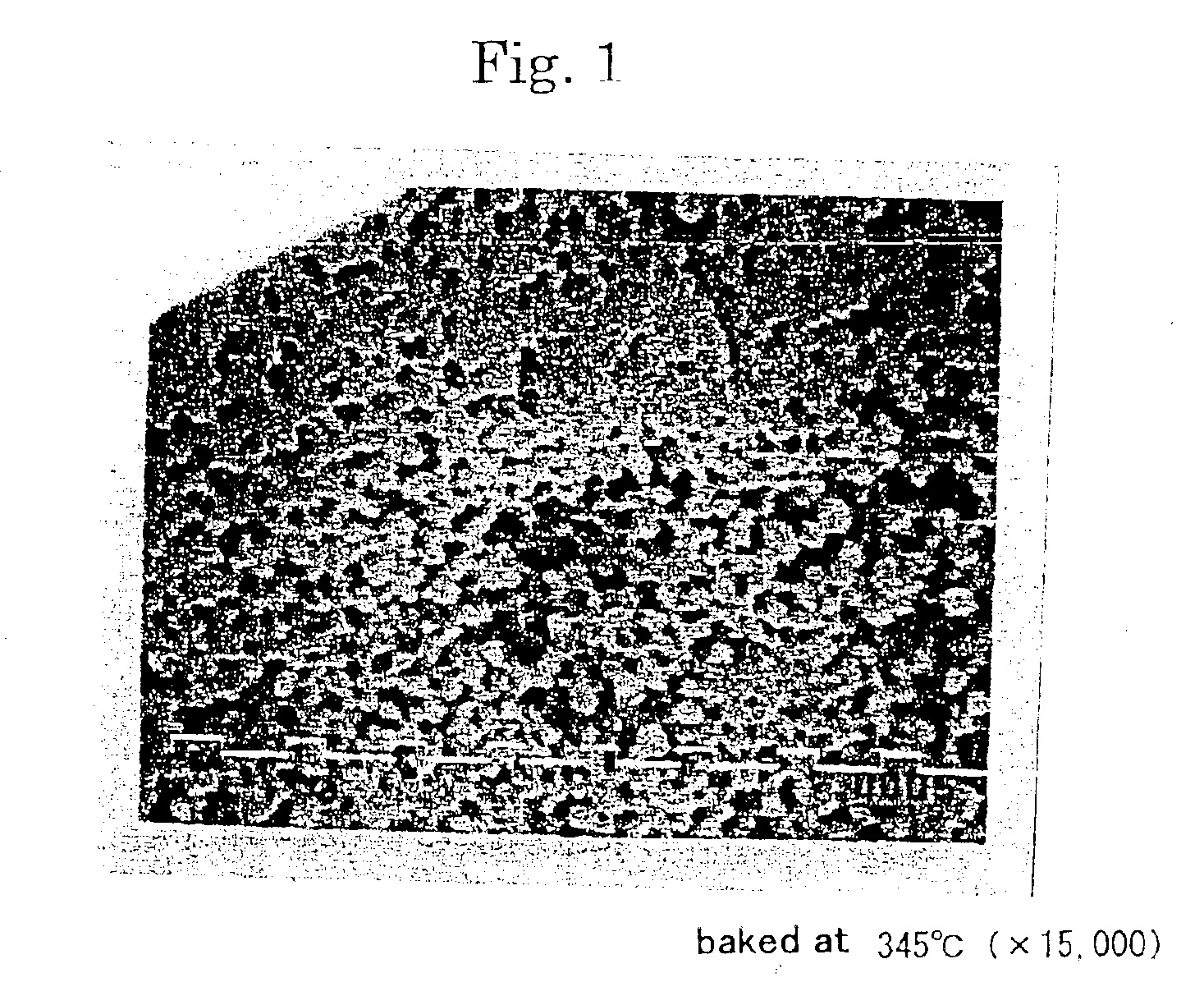
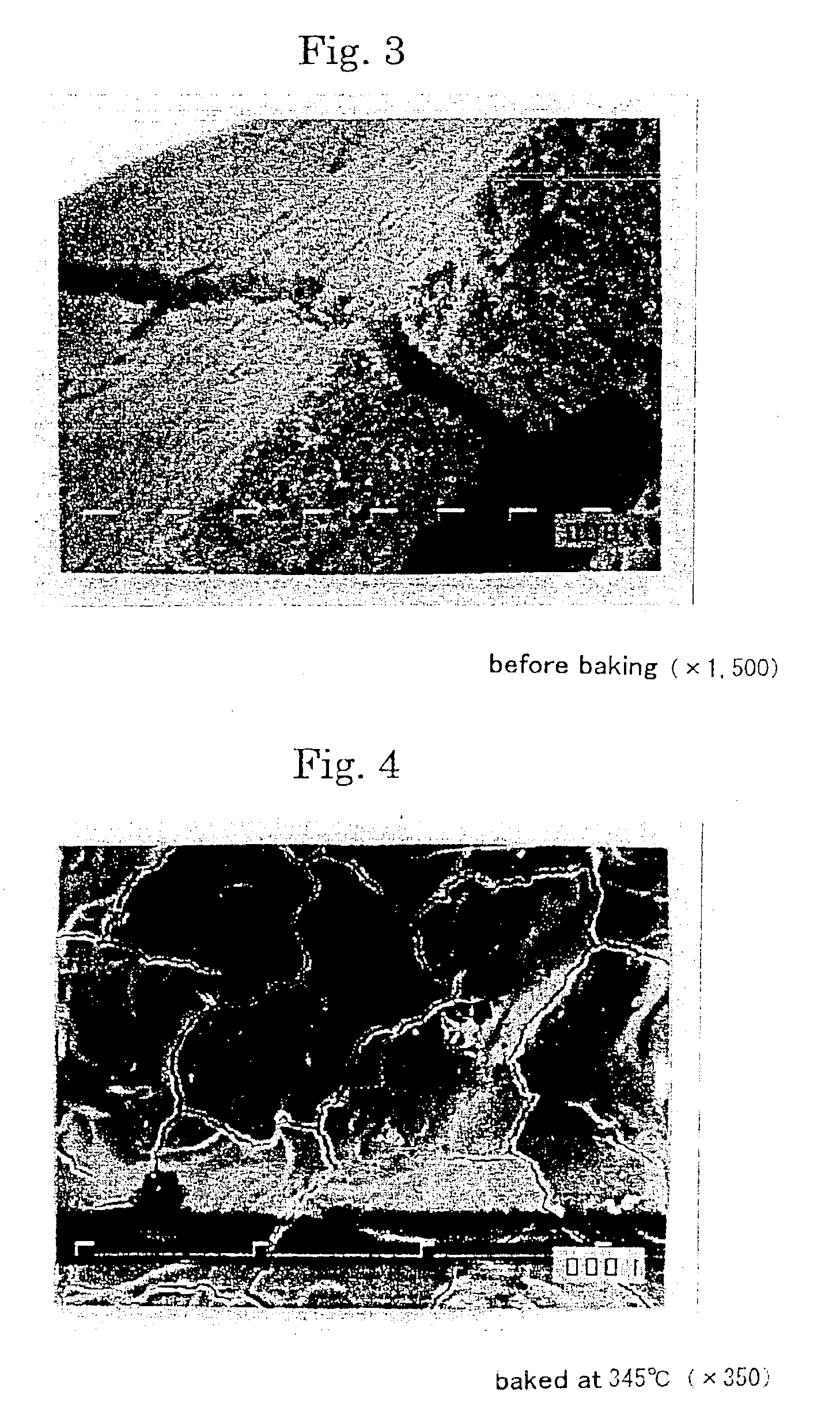
[0091]350 g of core particles of crushed activated carbon (between 20-mesh and 14-mesh) produced from the palm shell were introduced to a powder coating machine (“MP-01”, commercially available from POWREX CORPORATION), and the activated carbon particles were convected at air feeding temperature of 60° C., air feeding flow rate of 80 m3 / hr., and revolution speed of a tri-blade bottom rotor of 300 rpm to create convectional movement.

[0092]On the other hand, a suspension of polytetrafluoroethylene resin fine powder (“POLYFRON D-1”, commercially available from DAIKIN INDUSTRIES Co., Ltd.) was diluted with distilled water to prepare a suspension containing solid contents of 20% wt. 150 g of the suspension was sprayed along the tangential direction of the rotating bottom rotor over the convecting activated carbon particles at an injection rate of 9.5 g / min. from a dual fluid nozzle having a nozzle diameter of 1.2 mm. The first coating process was completed when the exhaust temperature wa...


PUM

PropertyMeasurementUnit
Pore sizeaaaaaaaaaa
Pore sizeaaaaaaaaaa
Pore sizeaaaaaaaaaa

Abstract

An adsorbent includes core particles containing an adsorbing material; a porous coating layer including a polymer material that coats the core particles; and an underlying layer containing a metal compound and disposed between the core particles and the porous coating layer. The porous coating layer is formed by spraying and applying a suspension or a solution containing the polymer material over the adsorbing material, or by immersing the adsorbing material into the suspension or the solution.

Description

BACKGROUND OF THE INVENTION[0001]1. Field of the Invention[0002]The present invention relates to adsorbents used for cleaning (deodorizing, decoloring and extracting impurities) of gases and liquids or for various other applications, methods for producing the same and applications thereof.[0003]More specifically, the present invention relates to indoor ambient air cleaning members, methods for cleaning air, air cleaning devices, dehumidifying materials for inner gas of dual-glass window, drying agents for organic solvents, adsorbents for hard disk drives and freshness keeping member, all of which utilize the adsorbents.[0004]The present invention also relates to ambiance humidity regulating members that provide controlled humidity of the ambiance when it is placed therein.[0005]2. Related Prior Art[0006]Adsorbents that are supported on a porous base member such as net sheets, fibers, foams and so on by utilizing binders and the like are known in the art. The adsorbents are utilized ...

Claims


Application Information

Patent Timeline
IPC IPC(8): B01J20/20B01J20/30B01J20/32B01D53/04B01J47/00G11B33/14
CPCB01D53/02B01J20/06B01J20/08B01J20/103B01J20/14B01J20/16B01J20/20B01J20/28019B01J20/2805B01J20/28078B01J20/305B01J20/3204B01J20/3236B01J20/3293B01J47/007G11B33/1453G11B33/146B01J20/261B01J20/262B01J20/264B01J20/327B01J20/3272B01J20/3276B01J20/3289B01J20/28004Y10T428/2998B01D2253/104B01D2253/106B01D2253/108B01D2253/112B01D2253/202B01D2253/206B01D2253/304B01D2253/308B01D2257/80B01D2257/90B01D2259/4146B01D2259/4508B01J2220/49B01D2253/102B01J47/018
Inventor NEMOTO, YASUSHIMORI, HISASHIKUWAHARA, TADASHI
Owner BRIDGESTONE CORP
Why Eureka
Try Eureka