Boiler improvements with oxygen-enriched combustion for increased efficiency and reduced emissions

US6907845B2Inactive Publication Date: 2005-06-21KREBS & SISLER LP

Image

  • Boiler improvements with oxygen-enriched combustion for increased efficiency and reduced emissions
  • Boiler improvements with oxygen-enriched combustion for increased efficiency and reduced emissions
  • Boiler improvements with oxygen-enriched combustion for increased efficiency and reduced emissions

Examples


Embodiment Construction

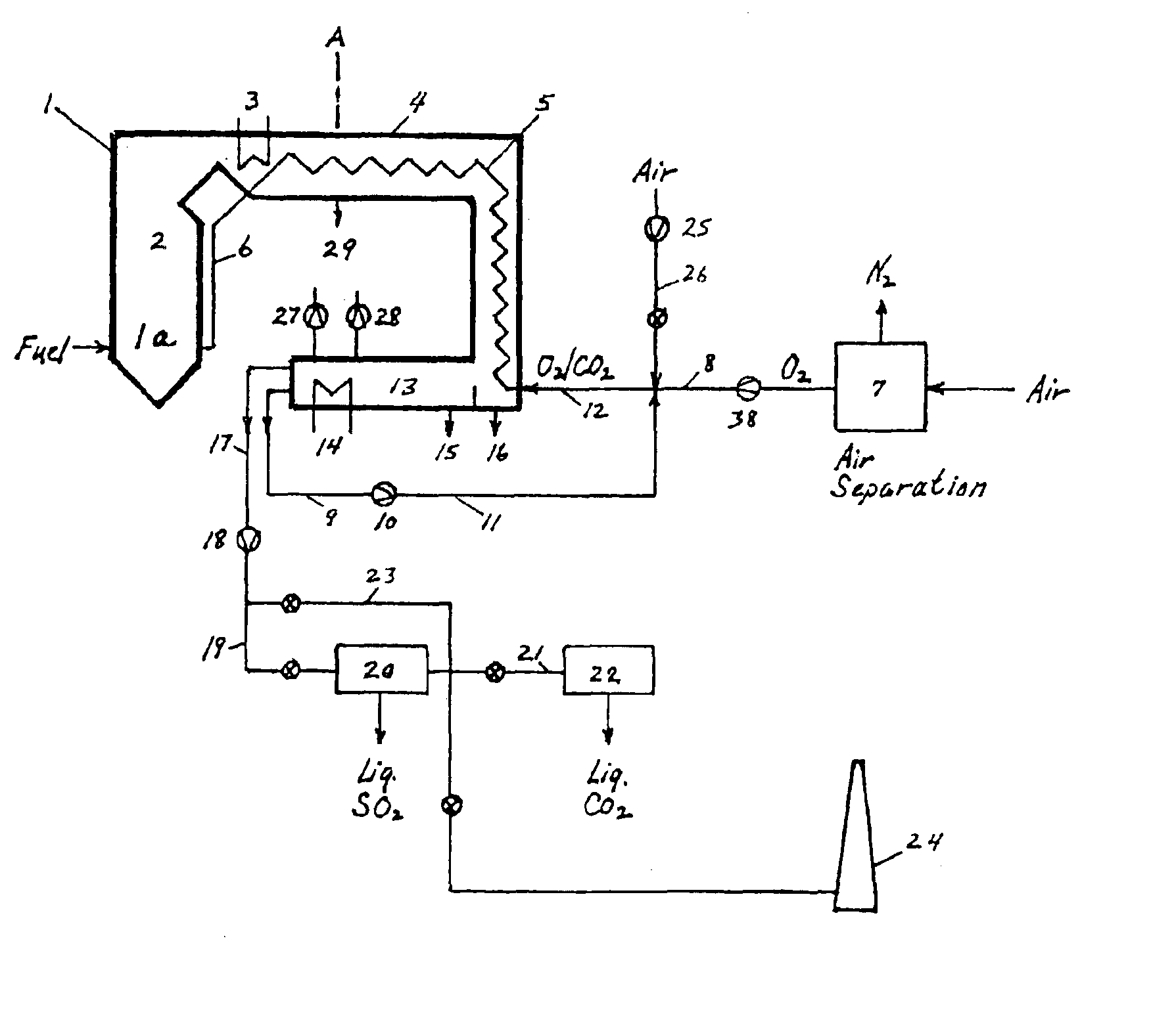
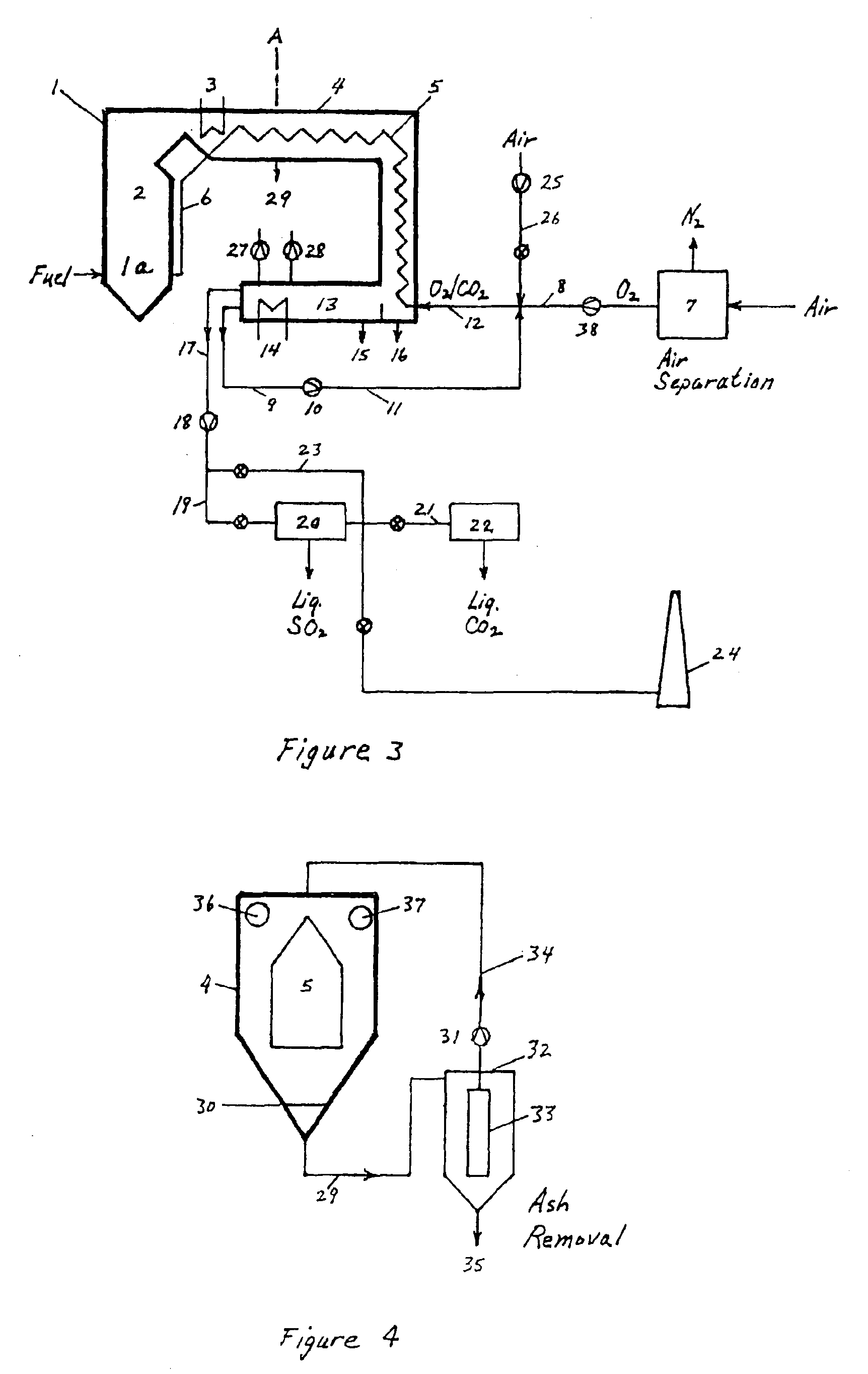
[0064]FIG. 3 shows a cross-sectional schematic diagram of a steam-generating boiler 1 combined with a Gas Primer Sector (GPS) 4. Boiler 1 includes a fuel combustion zone 1a, radiation zone 2 and a convection zone in the area of the boiler feedwater tubing 3. Fuel is supplied to the boiler in the lower region of radiation zone 2, and the fuel oxidant is delivered through an insulated duct 6.

[0065]The overall dimensions of the GPS are generally proportional to boiler size. For example: given a 100 MW scale state-of-art boiler designed by Babock & Wilcox, its height may be about 125 feet (38 m); the GPS may extend horizontally about 125 feet (38 m) from the top of the boiler, then downwardly about 125 feet (38 m), and again horizontally about 75 feet (23 m) in a lower gas cooling section, as illustrated in FIG. 3. A similar boiler designed for a 750 MW capability may have a height of 250 feet (76 m); the GPS may extend horizontally about 250 feet (76 m) from the top of the boiler, then...


PUM


Abstract

A method and apparatus to conduct 02 / CO2 combustion or oxygen-enriched combustion. The boiler exhaust gas passes through a Gas Primer Sector (GPS) combined with the boiler to effect heat transfer to the combustion gas in indirect counter-flow heat exchange. Sharply reduced gas flows result from using largely moisture-free CO2 as diluent for O2 in the combustion gas which allows long residence time at low velocity for maximum heat transfer from the exhaust gas to the combustion gas. Most particulate drops out and most moisture is condensed from the cooled mostly CO2 exhaust gas. The larger portion is blended with oxygen for the combustion gas and reheated and returned to the boiler through the integrated GPS; the smaller portion is cleaned and separated, the CO2 released or recovered. The complete exhaust gas-combustion gas cycle may be 30 to 90 seconds and preferably about 60 seconds. The high heat capacity of CO2 allows a much higher oxygen content in the combustion gas compared to open-cycle air combustion with a large nitrogen content of lower heat capacity. Efficiency is increased. Final exhaust gas separation and recovery is simplified. Condensate is processed to boiler feedwater or potable water quality. NOx, is eliminated, mercury fume captured and CO2 output reduced.

Description

[0001]This application is a continuation of International Application No. PCT / US03 / 032402 filed Oct. 14, 2003 which claims priority from U.S. Provisional Application Ser. No. 60 / 422,601, filed Oct. 30, 2002.FIELD OF THE INVENTION[0002]This invention relates to a method and apparatus integrated with a boiler for recovering sensible and latent heat from hot exhaust gas in heat exchange with cooled exhaust gas blended with oxygen for fuel combustion. The method allows the flexibility to burn virtually any fuel using oxygen-enriched air or pure oxygen and mostly CO2 mixtures while recovering fuel sulfur as liquid SO2. Highest efficiency is attained in 100% O2 / CO2 combustion.BACKGROUND OF THE INVENTIONReferences of InterestU.S. Patents[0003]U.S. Pat. No. 4,354,925 October 1982 Schorfheide[0004]U.S. Pat. No. 4,542,114 September 1985 Hegarty[0005]U.S. Pat. No. 5,732,571 March 1998 Maerz et al.[0006]U.S. Pat. No. 6,202,574 March 2001 Liljedahl et al.[0007]U.S. Pat. No. 6,418,865 July 2002 M...

Claims


Application Information

Patent Timeline
21 Jun 2005
Publication
US6907845B2
IPC
F23J15/06; F23N5/00; F23L7/00; F23J15/02
CPC
F23J15/06; F23L7/007; F23N5/003; F23J2900/15061; F23L2900/07001; F23L2900/15043; Y02T50/677; F23N2033/04
Inventors
KREBS, WILLIAM P.