
Aqueous binder formulation for metal and ceramic feedstock for injection molding and aqueous coating composition

Active Publication Date: 2006-01-17
UNITED MATERIALS TECH
View PDF12 Cites 18 Cited by
  • Summary
  • Abstract
  • Description
  • Claims
  • Application Information

AI Technical Summary

Benefits of technology

[0008]This invention pertains to a low cost aqueous binder system for shaping metal and ceramic parts from powders, and molding compositions therefor. More particularly, the invention is directed to molding compositions containing low cost aqueous binder for forming high quality, complex articles which exhibit sufficient green strength and which can be readily sintered without experiencing cracking, distortion, to near theoretical density. In contrast, the invention reduces the high cost associated with prior art by 33% and reduces the molding cycle time by 25%.
[0013]This invention also presents an aqueous metal and / or ceramic coating formulation which is used to form an in-situ thick or thin layer of selected material such as: titanium carbide, tungsten carbide, tantalum, stainless steels, non-ferrous alloy, molybdenum or multi layers of metal and ceramic on a molded green part. Then, it is co-sintered to near full density. This presents an easy, low cost and quick technique to create or design in-situ multi surface layer properties on a single part for specific applications. The binder used in the formulation of this coating slurry is edible gelatine and it is environmentally safe during debinding. This commercially available gelatine is comprised of 84–90% protein, 8–12% water and 2–3% mineral salts.
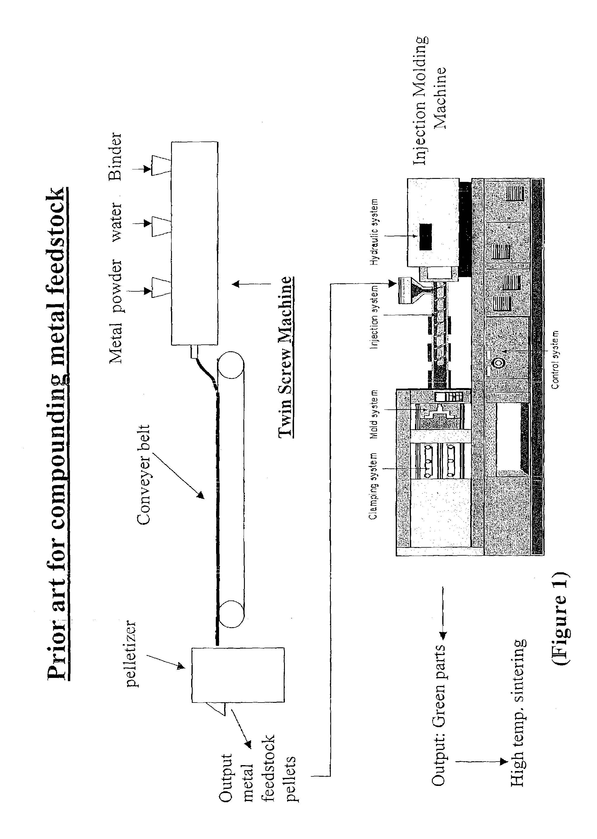
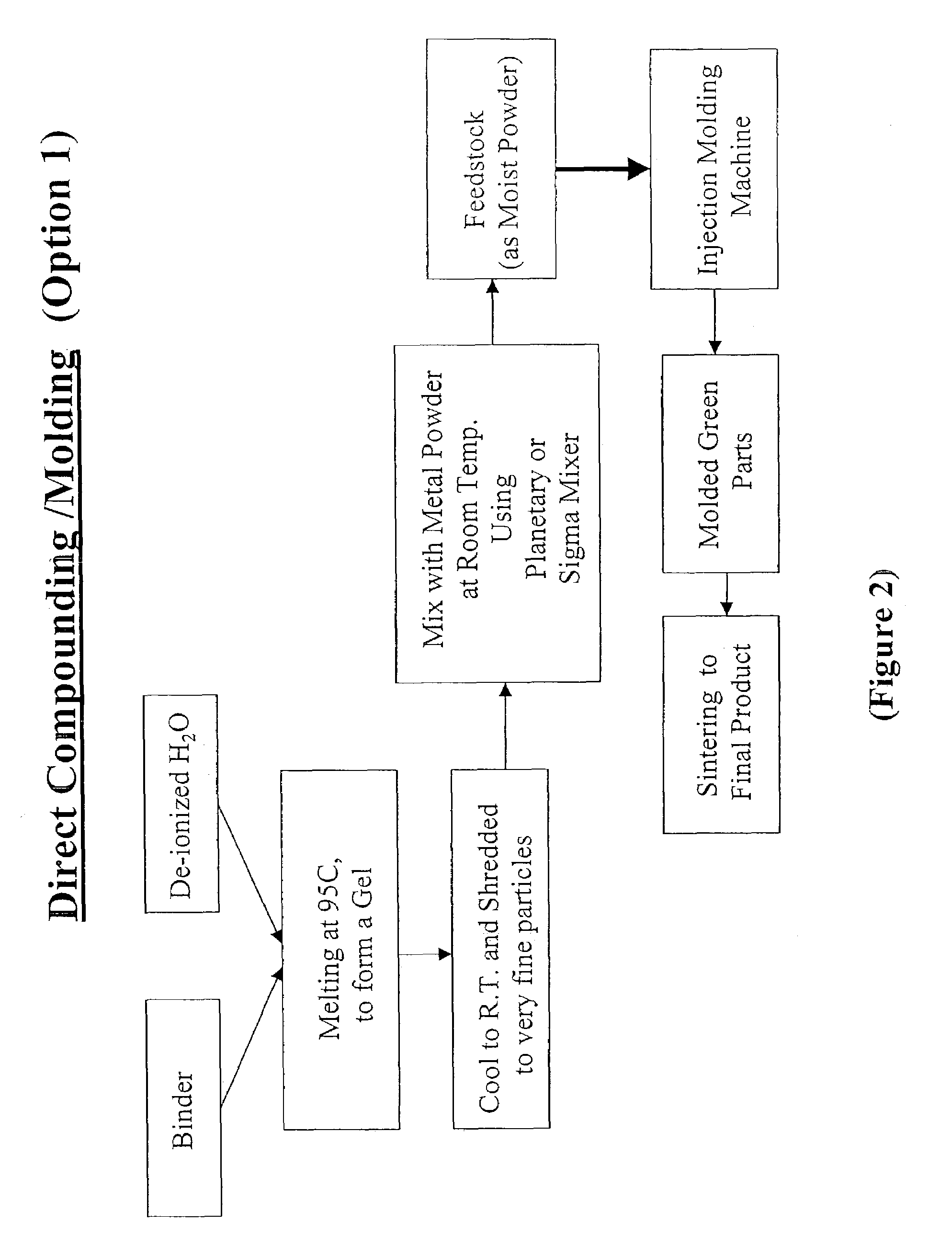
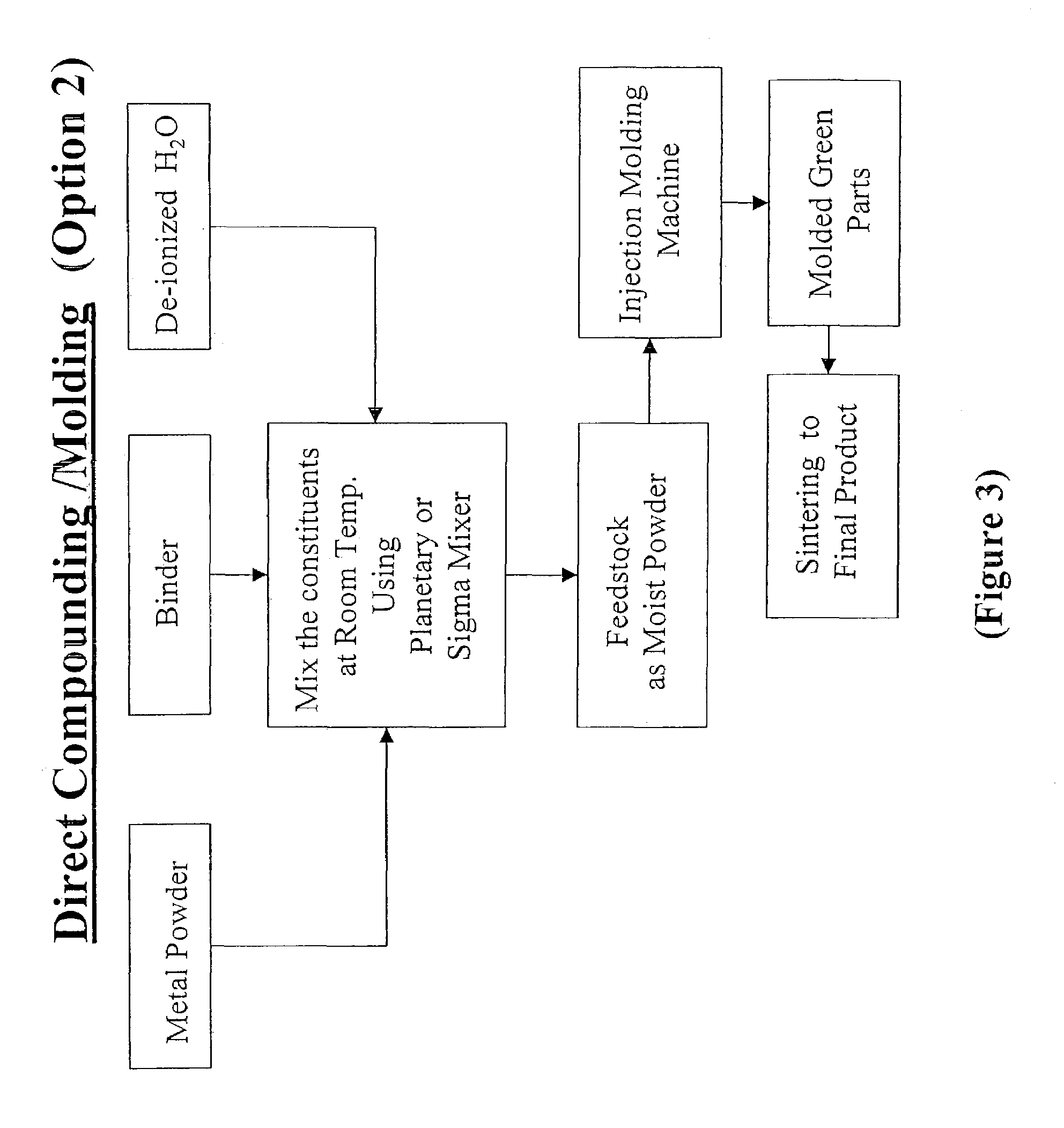
[0014]This invention provides the DCM process by premixing metal powder with hydrated (5 to 10 wt % deionzed water) binder powder at room temperature. The mixture is directly fed into the hopper of an injection molding machine. The mixture is melted in the barrel of the machine at 70–98° C. and then injected into a mold cavity. The mold temperature is maintained lower than room temperature (10–24° C.). The DCM process reduces the feedstock production cost by eliminating the use of a twin screw extruder for compounding. Simplicity of this process allows for better processing control.

Problems solved by technology

This initial step of the firing process may have an adverse influence on the quality of the post-molding sintered parts.
This step requires exclusive equipment and very long binder burnout time to avoid the development of creaks in the part.
However, higher cost associated with agaroid binder system, significantly reduces the profit margin of the final product.
Also, the low gelling temperature (35–39° C.) of agaroid binder system prolongs the molding cycling time, which adversely effects the production rate.

Method used


Image

  • Aqueous binder formulation for metal and ceramic feedstock for injection molding and aqueous coating composition
  • Aqueous binder formulation for metal and ceramic feedstock for injection molding and aqueous coating composition
  • Aqueous binder formulation for metal and ceramic feedstock for injection molding and aqueous coating composition

Examples


example 1

[0041]A batch of feedstock was prepared using 10 kg of 17–4 PH stainless steel powder having an average particle size of 15 micron. A total of 180 g binder with a ratio of 2.2 of colloid 710H to glucose was mixed with 1132 g of in-situ water containing 2 g of sodium tetraborate to adjust the pH of the water to about 9.4 and 1.5 g potassium chloride. Also, a mixture of 0.12 g potassium sorbate and 0.12 g sodium benzoate were added as biocides to inhibit the growth of molds and bacteria. The 180 g binder and biocides were pre-mixed with the in-situ water. This mixture was transferred into a sigma blender and mixed for 10 minutes at room temperature. Then the temperature was raised to 93–98° C. (200–208° F.). The mixing was continued for 15–25 minutes and allowed the binder to melt. The metal powder was added to the mixer in two steps. Initially 4.5 kg of the metal powder was added into the mixer and blended with the binder for 15 minutes, and then the remaining of the metal powder (2....

example 2

[0043]Portion of the feedstock material from example 1 was molded to make 140 parts using two cavity steel mold. The parts molded at 800 psi (5.6×10³ KN / m2) injection pressure and 300 psi (2.1×10³ KN / m2) pack pressure. The barrel temperature was 90° C. (194° F.) and mold temperature was 24° C. (75.2° F.). Initially, the cooling time (the time parts stay in the mold after injection cycle) was set to 15 seconds. The cooling time gradually reduced after every 25 shots. The lowest cooling time that the part could be ejected and remove from the mold cavity was about 6 seconds. The yield of this molding trial was >98%. The average part weight was 3.61±0.04 grams. A sintering experiment conducted on 30 of these parts under the following conditions to determine the final density and shrinkage.

[0044]

TemperatureHolding Time (hr.)Atmosphere 25° C.0Nitrogen450° C.3.5Nitrogen switch to hydrogen750° C.1Hydrogen1340° C. 1.0Hydrogen900° C.5 min.Hydrogen switch to nitrogen 25° C.0Nitrogen

The average...

example 3

Composite Feedstock

[0045]This example illustrates the application of the invention for preparation of aqueous stainless steel / titanium carbide feedstock material. Stainless steel 17–4 PH and titanium carbide powders having average particle size of 15 micron and 3.8 micron respectively were used in this example. 100 g of the same Colloid binder composition as example 1 was mixed with 505 g of in-situ H2O, 0.1 g potassium sorbate and 0.1 g sodium benzoate in a sigma blender. The temperature was raised to 93–98° C. (200–208° F.) which melted the binder. A mixture of 4200 grams 17–4 PH powder with 800 grams of titanium carbide powder was added to the melted binder. The mixing continued for about 50 minutes to produce homogeneous materials. The material was cooled to 32–37° C. (90–100° F.) before removing it from the sigma mixer. The material was shredded twice to produce uniform small pieces of feedstock. The moisture content of the feedstock adjusted to 8.3%. Spiral experiment conducte...


PUM

PropertyMeasurementUnit
Percent by massaaaaaaaaaa

Abstract

Additionally, a coating composition comprising gelatine, water and a metal and / or ceramic powder is used to form coating layers on selected materials.

Description

RELATED APPLICATIONS[0001]This application claims the benefit of U.S. patent application Ser. No. 10 / 300,710, filed Nov. 20, 2002, now abandoned.BACKGROUND OF THE INVENTION[0002]Various forming techniques are being used for fabrication of metal and ceramic parts. In the manufacturing of many metal and ceramic articles, a “green” body is formed of powder, binder, and possibly other ingredients. The green body is then typically fired to remove the binder and sinter to form the dense metal or ceramic articles. One of the desired methods to make green bodies is an injection molding process.[0003]In injection molding, a mixture of metal and / or ceramic powder and binder is injected into a mold corresponding to the desired green body shape. Typically the mixture is heated to lower its viscosity before molding. The mixture is allowed to harden in the mold, and the mold is then opened to remove the green body from the mold cavity. The green body is then fired to remove the binder and sinter ...

Claims


Application Information

Patent Timeline
IPC IPC(8): C09D189/00
CPCC09D189/00
Inventor BEHI, MOHAMMAD
Owner UNITED MATERIALS TECH
Learn More