

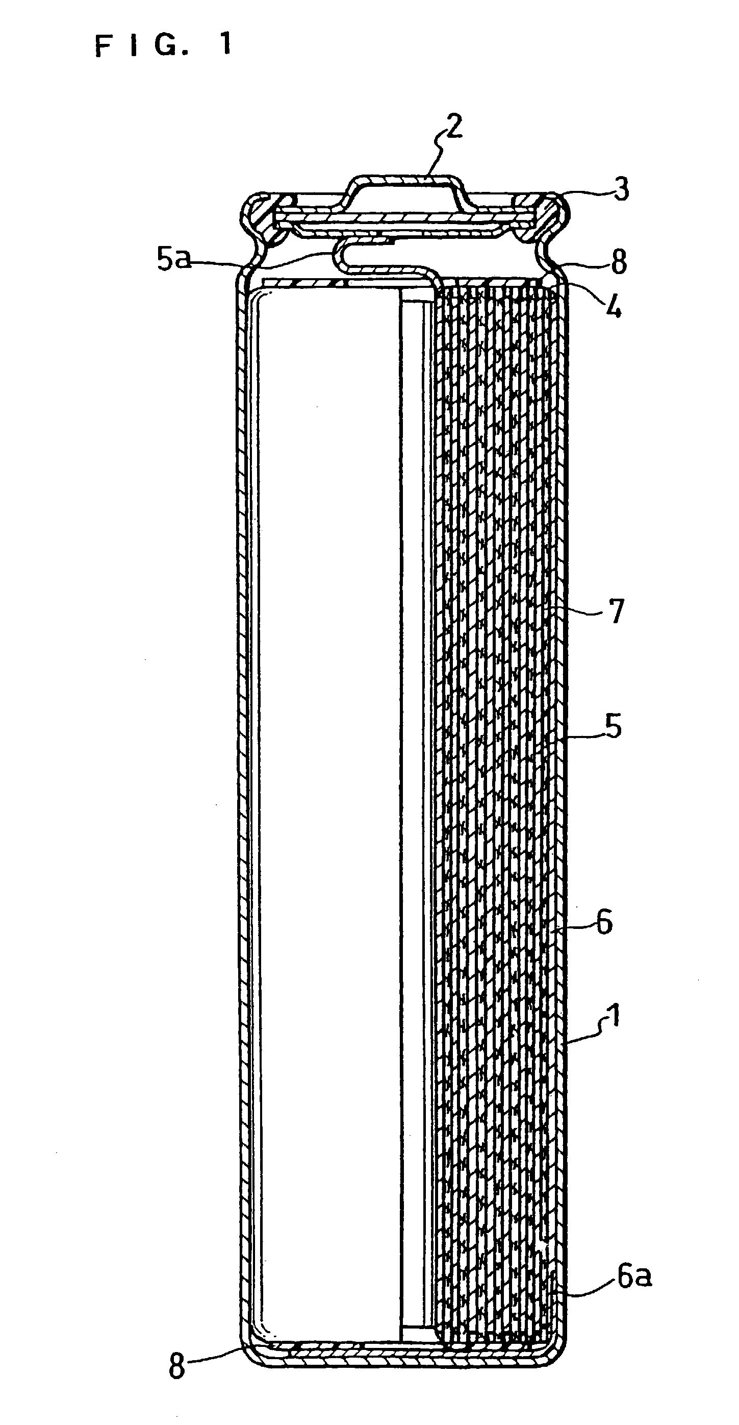
Non-aqueous electrolyte secondary battery
a secondary battery and electrolyte technology, applied in the field of non-aqueous electrolyte secondary batteries, can solve the problems of troublesome structure, difficult cutting costs, and excessive heat generation, and achieve the effect of sufficiently maintaining the high rate characteristics of the battery, easy control of the strength of the electrode plate and the temperature coefficient of resistan
- Summary
- Abstract
- Description
- Claims
- Application Information
AI Technical Summary
Benefits of technology
Problems solved by technology
Method used
Image

Examples
example 1
(i) Positive Electrode
[0061]Acetylene black serving as the conductive particulate material and polyethylene serving as the binder polymer and having a softening temperature of 120° C. were mixed in a weight ratio of 10:1, and a proper amount of carboxymethyl cellulose was added thereto as the thickener to give a paste like mixture.
[0062]Both sides of a 10 μm thick aluminum foil serving as the positive electrode current collector were coated with the aforementioned mixture to a thickness of 5 μm or less, and dried to yield a resistance layer.
[0063]The positive electrode material mixture was prepared by mixing 100 parts by weight of LiCoO2 powder, 3 parts by weight of acetylene black and 7 parts by weight of fluorocarbon resin type binder (polytetrafluoroethylene) with a proper amount of carboxymethyl cellulose aqueous solution. The above-mentioned LiCoO2 powder was synthesized by calcining a mixture of Li2CO3 and Co3O4 at 900° C. for 10 hours.
[0064]Both sides of the positive electrod...
example 2
[0071]Cylindrical batteries were constructed as in Example 1 except that 3-chlorothiophene, furan, o-terphenyl, m-terphenyl, p-terphenyl, diphenyl ether, 2,3-benzofuran, bis(p-tolyl)ether, diallyl ether, allyl butyl ether, 3-phenoxy toluene or cyclohexyl benzene was used as the additive. They were named as Batteries 2 to 13. C / A value of Batteries 2 to 13 was also 3.54 mAh / cm2, which was the same as that of Battery 1.
example 3
[0072](i) Both sides of 10 μm thick aluminum foil serving as the positive electrode current collector were directly coated with the same positive electrode material mixture as that in Example 1, dried and rolled with pressure to give a positive electrode having a thickness of 0.16 mm, a width of 55 mm and a length of 540 mm. Accordingly, this electrode does not have a resistance layer.
[0073](ii) Nickel powder serving as the conductive particulate material and polyethylene serving as the binder polymer and having a softening temperature of 120° C. were mixed in a weight ratio of 10:1, and a proper amount of carboxymethyl cellulose was added thereto as the thickener to give a paste like mixture.
[0074]Both sides of 10 μm thick copper foil serving as the negative electrode current collector were coated with the aforementioned mixture to a thickness of 5 μm or less, and dried to provide a resistance layer.
[0075]Both sides of the negative electrode current collector having the obtained re...
PUM
| Property | Measurement | Unit |
|---|---|---|
| resistivity | aaaaa | aaaaa |
| temperature | aaaaa | aaaaa |
| thickness | aaaaa | aaaaa |
Abstract
Description
Claims
Application Information