Implantable medical device with drug filled holes

a technology of implantable medical devices and holes, which is applied in the field of therapeutic agent delivery devices, can solve the problems of increasing trauma and risk to patients, restenosis is a major complication, and the surface coating can provide little actual control over the release kinetics of beneficial agents

Inactive Publication Date: 2007-04-24
CONOR MEDSYST
View PDF373 Cites 134 Cited by
  • Summary
  • Abstract
  • Description
  • Claims
  • Application Information

AI Technical Summary

Benefits of technology

[0020]In another preferred embodiment, the bioerodible matrix substantially prevents the ingress of water or enzymes.
[0025]In still another preferred embodiment, the protective layer further comprises an activating or a deactivating agent, wherein the activating or deactivating agent prevents the loss of biological function of the first or second therapeutic agents, preferably the activating or deactivating agents are selected from the group consisting of antacids, buffers, enzyme inhibitors, hydrophobic additives, and adjuvants, more preferably the activating or deactivating agent is an antacid that protects one of said first and second therapeutic agents from a deactivating decrease in pH. Alternatively, the protective layer comprises an activating or deactivating agent that prevents deactivating interactions between said first and second therapeutic agents.

Problems solved by technology

Restenosis is a major complication that can arise following vascular interventions such as angioplasty and the implantation of stents.
To treat this condition, additional revascularization procedures are frequently required, thereby increasing trauma and risk to the patient.
The patent offers detailed descriptions of methods for coating stent surfaces, such as spraying and dipping, as well as the desired character of the coating itself: it should “coat the stent smoothly and evenly” and “provide a uniform, predictable, prolonged release of the anti-angiogenic factor.” Surface coatings, however, can provide little actual control over the release kinetics of beneficial agents.
However, the increased coating thickness results in increased overall thickness of the stent wall.
This is undesirable for a number of reasons, including increased trauma to the vessel wall during implantation, reduced flow cross-section of the lumen after implantation, and increased vulnerability of the coating to mechanical failure or damage during expansion and implantation.
Coating thickness is one of several factors that affect the release kinetics of the beneficial agent, and limitations on thickness thereby limit the range of release rates, duration of drug delivery, and the like that can be achieved.
In addition to sub-optimal release profiles, there are further problems with surface coated stents.
Since these beneficial agents are frequently highly cytotoxic, sub-acute and chronic problems such as chronic inflammation, late thrombosis, and late or incomplete healing of the vessel wall may occur.
Additionally, the carrier polymers themselves are often highly inflammatory to the tissue of the vessel wall.
On the other hand, use of biodegradable polymer carriers on stent surfaces can result in the creation of “virtual spaces” or voids between the stent and tissue of the vessel wall after the polymer carrier has degraded, which permits differential motion between the stent and adjacent tissue.
Resulting problems include micro-abrasion and inflammation, stent drift, and failure to re-endothelialize the vessel wall.
Another significant problem is that expansion of the stent may stress the overlying polymeric coating causing the coating to plastically deform or even to rupture, which may therefore effect drug release kinetics or have other untoward effects.
Further, expansion of such a coated stent in an atherosclerotic blood vessel will place circumferential shear forces on the polymeric coating, which may cause the coating to separate from the underlying stent surface.
Such separation may again have untoward effects including embolization of coating fragments causing vascular obstruction.
In addition, it is not currently possible to deliver some drugs with a surface coating due to sensitivity of the drugs to water, other compounds, or conditions in the body which degrade the drugs.
For example, some drugs lose substantially all their activity when exposed to water for a period of time.
When the desired treatment time is substantially longer than the half life of the drug in water the drug cannot be delivered by know coatings.
These drugs which are sensitive to compounds or conditions in the body often cannot be delivered using surface coatings.

Method used


Image

  • Implantable medical device with drug filled holes
  • Implantable medical device with drug filled holes
  • Implantable medical device with drug filled holes

Examples


example 1

Formulation Comprising a Therapeutic Agent within the Protective Layer

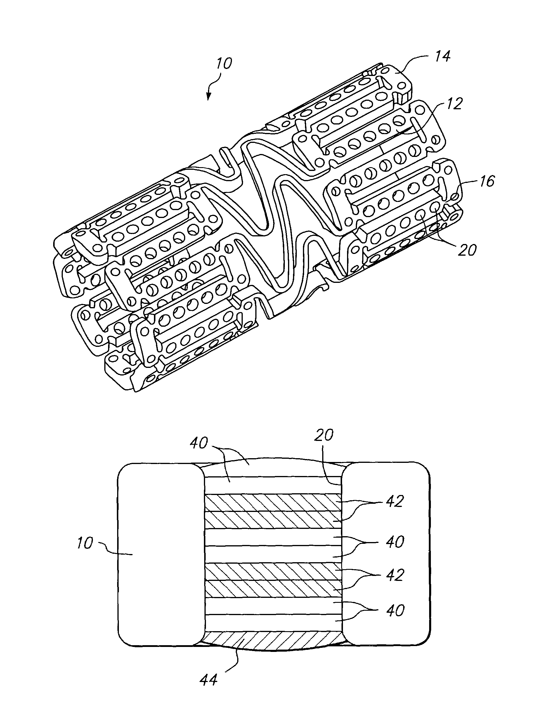
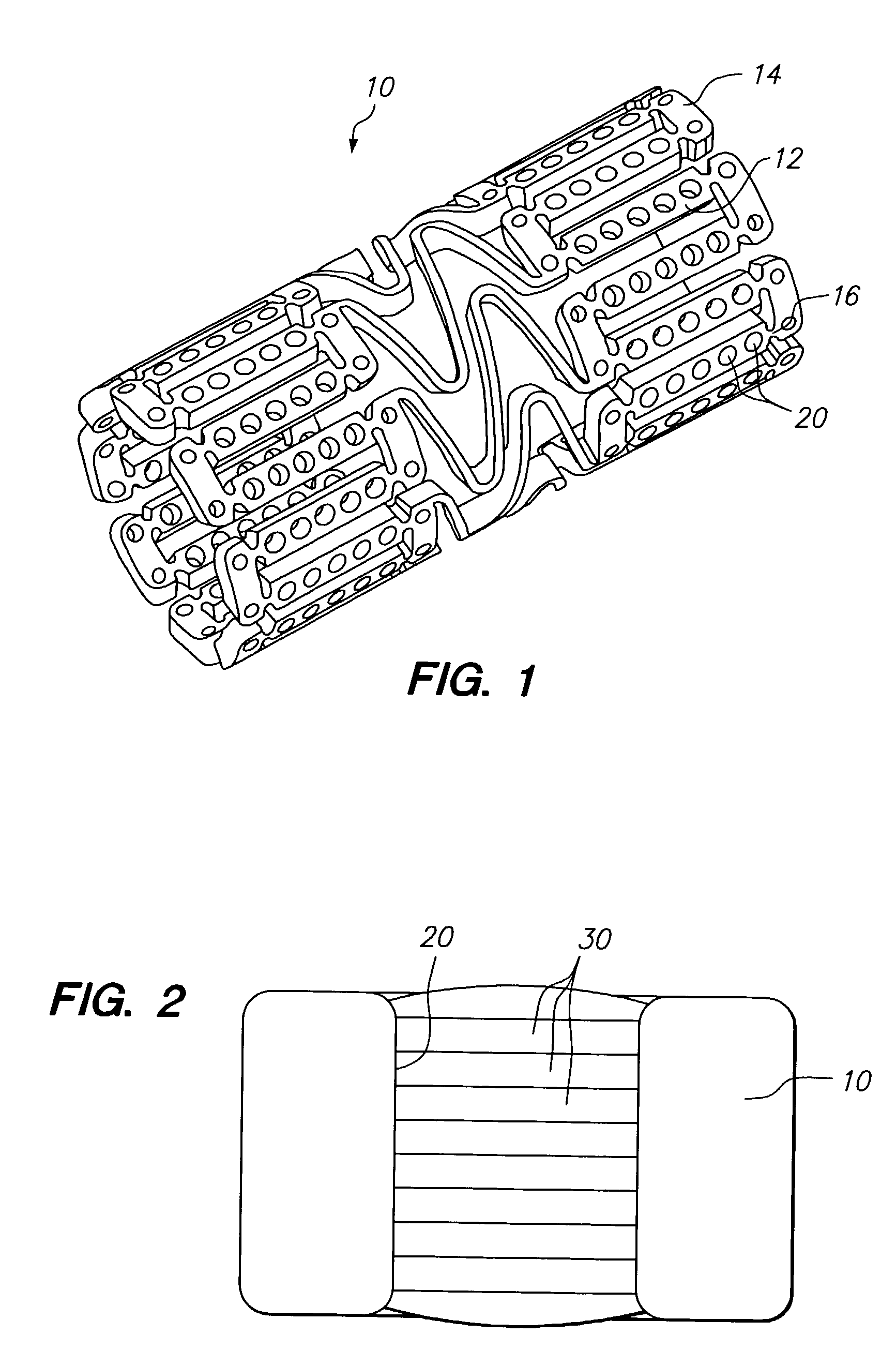
[0100]A first mixture of poly(lactide-co-glycolide) (PLGA) (Birmingham Polymers, Inc), lactide:glycolide: 85:15, (Mv>100,000 Daltons) 7% wt. and a suitable organic solvent, such as DMSO, NMP, or DMAC 93% wt. is prepared. The mixture is loaded dropwise into holes in the stent, then the solvent is evaporated to begin formation of the barrier layer. A second barrier layer is laid over the first by the same method of filling polymer solution into the hole followed by solvent evaporation. The process is continued until five individual layers have been laid down to form the barrier layer.

[0101]A second mixture of a limus, such as sirolimus, 3% solids basis, and dipalmitoyl phosphatidylcholine (DPPC), 7% solids basis, in a suitable organic solvent, such as DMSO, is introduced into holes in the stent over the barrier layer. The solvent is evaporated to form a drug filled protective layer and the filling and evaporation pr...

example 2

Formulation Comprising Therapeutic Agents in Therapeutic Agent Layers and a Protective Layer Separating the Therapeutic Agent Layers

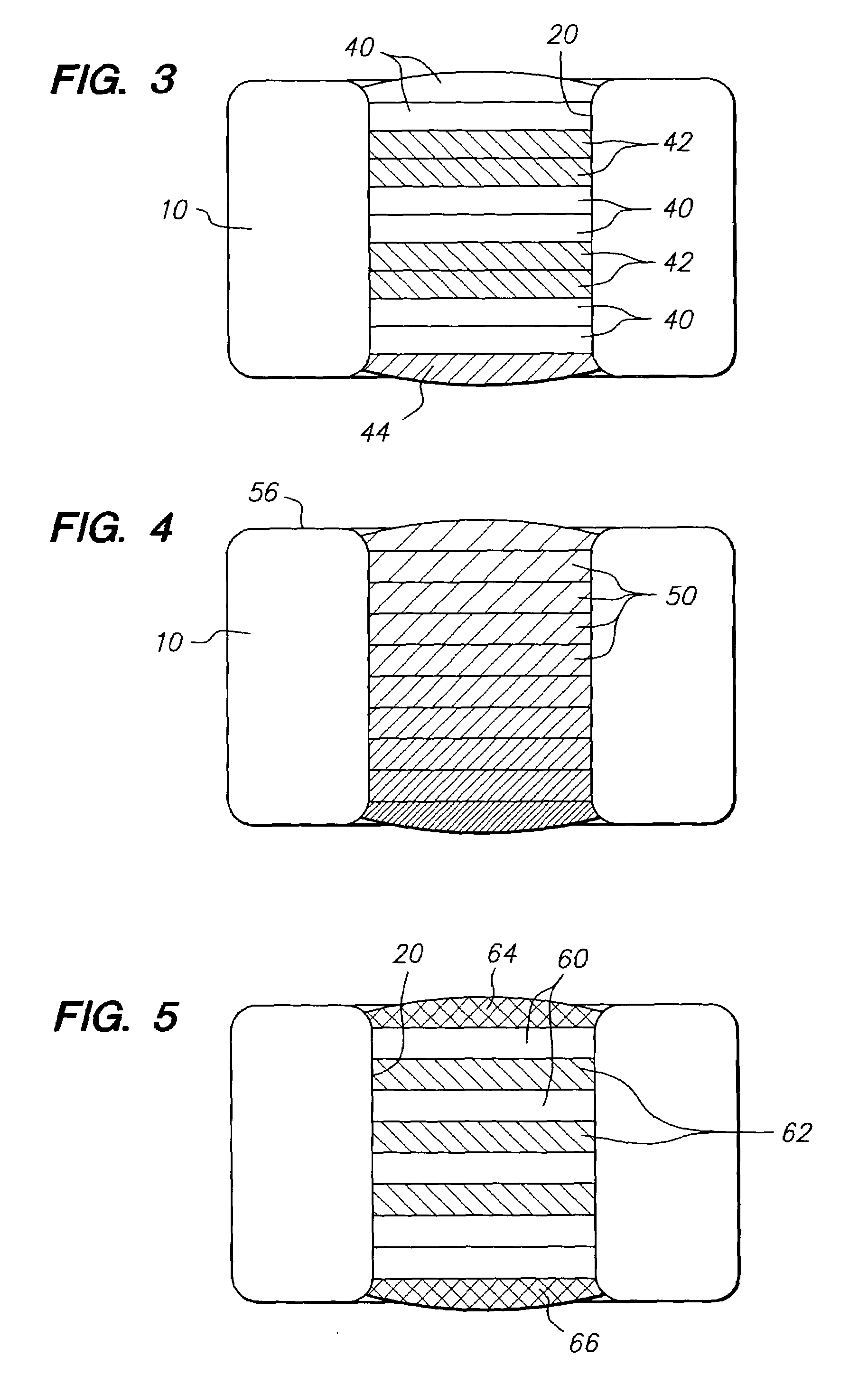
[0104]A first mixture of poly(lactide-co-glycolide) (PLGA), lactide:glycolide: 85:15, (Mv>100,000 Daltons) 7% wt. and a suitable organic solvent, such as DMSO, 93% wt. is prepared. The mixture is loaded drop-wise into holes in the stent, and the solvent is then evaporated to form the barrier layer. A second barrier layer is laid over the first by the same method of filling polymer solution into the hole followed by solvent evaporation. The process is continued until five individual layers have been laid down to form the barrier layer.

[0105]A second mixture of an PCN-1 ribozyme, 8% solids basis, and poly(vinylpyrrolidone) (PVP), molecular weight 8,000 daltons, 2% solids basis, in an mixed solvent of RNA-ase / DNA-ase free water, 50% vol., and dimethyl sulfoxide (DMSO), 50% vol., is introduced into holes in the stent over the barrier layer. The solvent is e...

example 3

Formulation Comprising a Therapeutic Agent in a Therapeutic Agent Layer and a Protective Layer Containing an Activating Agent

[0110]A first mixture of high molecular weight poly(lactide-co-glycolide) (PLGA), lactide:glycolide: 50:50 (Mv>100,000 Daltons), 7% wt. and a suitable organic solvent, such as DMSO, 93% wt. is prepared. The mixture is loaded drop-wise into holes in the stent, then the solvent is evaporated to form the barrier layer. A second barrier layer is laid over the first by the same method of filling polymer solution into the hole followed by solvent evaporation. The process is continued until five individual layers have been laid down to form the complete barrier layer.

[0111]A second mixture of chymotrypsin, 3% solids basis, and polyvinyl pyrrolidone, 7% solids basis, in a solvent mixture of water:DMSO: 50:50 is introduced into holes in the stent over the barrier layer. The solvent is evaporated to form an activating ester hydrolytic enzyme filled protective layer and ...


PUM

PropertyMeasurementUnit
thicknessaaaaaaaaaa
thicknessaaaaaaaaaa
thicknessaaaaaaaaaa

Abstract

The present invention relates to implantable medical devices for delivery of therapeutic agents, such as drugs, to a patient. More particularly, the invention relates to a device having therapeutic agents protected by a protective layer that prevents or retards processes that deactivate or degrade the active agents.

Description

FIELD OF THE INVENTION[0001]The invention relates to a therapeutic agent delivery device for delivery of agents, such as drugs, to a patient, and more particularly, the invention relates to a device having therapeutic agents separated by a protective layer.DESCRIPTION OF THE RELATED ART[0002]Implantable medical devices are often used for delivery of a beneficial agent, such as a drug, to an organ or tissue in the body at a controlled delivery rate over an extended period of time. These devices may deliver agents to a wide variety of bodily systems to provide a wide variety of treatments.[0003]One of the many implantable medical devices which have been used for local delivery of beneficial agents is the coronary stent. Coronary stents are typically introduced percutaneously, and transported transluminally until positioned at a desired location. These devices are then expanded either mechanically, such as by the expansion of a mandrel or balloon positioned inside the device, or expand...

Claims


Application Information

Patent Timeline
Patent Type & Authority Patents(United States)
IPC IPC(8): A61F2/06A61F2/00A61F2/84A61F2/02A61L31/10A61L31/14A61L31/16
CPCA61F2/91A61F2/915A61L31/10A61L31/148A61L31/16A61F2/2493A61F2002/91541A61F2002/91558A61F2210/0004A61F2250/003A61F2250/0031A61F2250/0068A61L2300/416A61L2300/604A61L2300/608
Inventor SHANLEY, JOHN F.PARKER, THEODORE L.
Owner CONOR MEDSYST
Why Eureka
Try Eureka