Electrodeposited copper foil with carrier foil

a carrier foil and copper foil technology, applied in the direction of insulating substrate metal adhesion improvement, transportation and packaging, other domestic articles, etc., can solve the problems of affecting the adhesion migration might occur, and the fine copper particles b>4/b> might constitute an obstacle, so as to improve the adhesion strength, and improve the adhesion. the effect of the insulating layer

Active Publication Date: 2010-04-06
MITSUI MINING & SMELTING CO LTD
View PDF17 Cites 26 Cited by
  • Summary
  • Abstract
  • Description
  • Claims
  • Application Information

AI Technical Summary

Benefits of technology

[0013]According to a study by the present inventors, it has been ascertained that basically, the higher the nickel content, the better adhesive strength, chemical resistance, humidity resistance and solder heat resistance will be, and that chemical resistance and solder heat resistance tend to deteriorate with increasing zinc content. And it has become apparent that when a passivated layer of nickel and zinc is formed, it is preferred from a practical standpoint that when the total deposited amount of nickel and zinc is 20 to 100 mg / m2, the passivated layer contain nickel and zinc at a ratio of nickel to zinc in the range of 6:4 to 8:2. When the nickel ratio exceeds 80%, an etching residue tends to be formed during circuit formation. Also, when the zinc ratio exceeds 40%, chemical resistance and solder heat resistance deteriorate, making the copper clad impracticable.
[0014]In the passivated layer of the electrodeposited copper foil with a carrier foil of the present invention, a chromate layer is formed on a nickel-zinc alloy layer and it is desirable that a silane coupling agent-adsorbed layer in which an amino functional silane coupling agent is adsorbed on the surface of the passivated layer be formed. The chromate layer and the silane coupling agent-adsorbed layer further improve the adhesion to the insulating layer and it is possible to improve humidity resistance and chemical resistance.

Problems solved by technology

However, it is feared that even these fine copper particles 4 might constitute an obstacle to the formation of ultrafine circuits which are considered to be required in the future.
As a result, it is feared that migration might occur or that in an extreme case, a short circuit might be induced.
In this passivated layer formed from a nickel-zinc alloy, the adhesion to special substrates cannot be improved very much when the nickel content is less than 50% by weight, whereas when the nickel content exceeds 99% by weight, the tendency toward occurrence of an etching residue becomes strong and this is undesirable.

Method used


Image

  • Electrodeposited copper foil with carrier foil
  • Electrodeposited copper foil with carrier foil
  • Electrodeposited copper foil with carrier foil

Examples


first embodiment

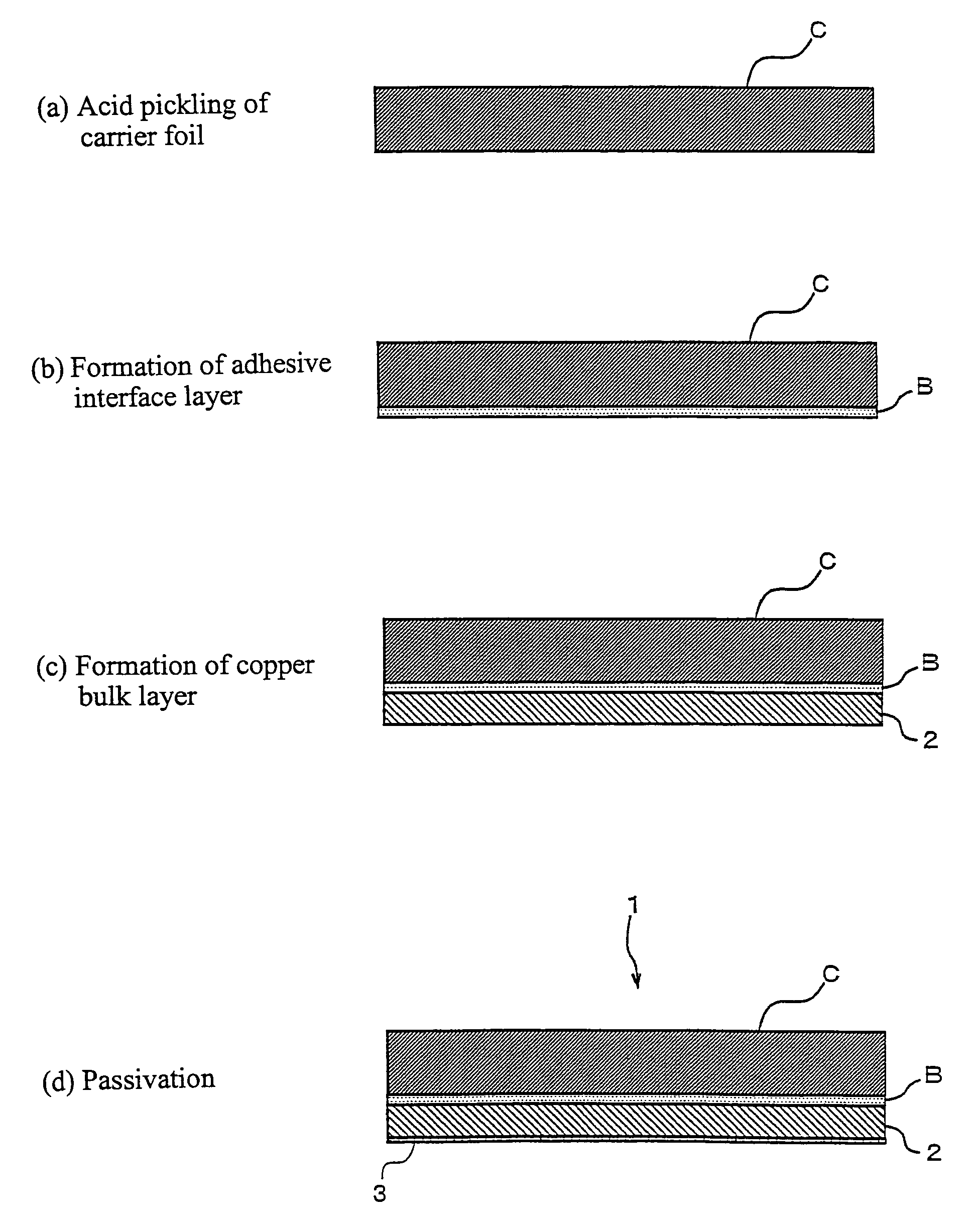
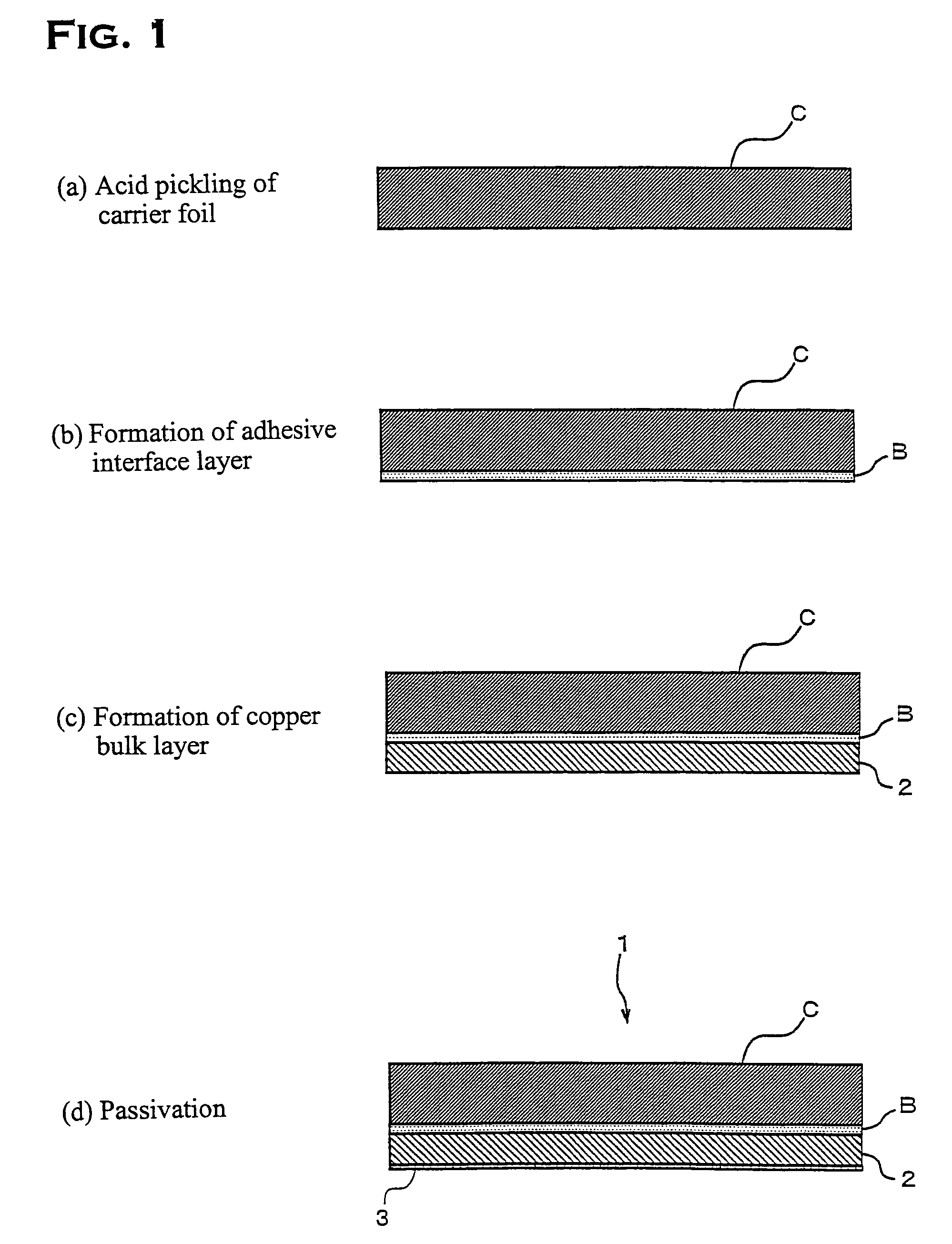
[0027]In this embodiment, electrodeposited copper foil 1 with a carrier foil related to the invention was fabricated by following the procedure shown in FIG. 1. First, in the step shown in (a) of FIG. 1, 18 μm thick copper foil was used as carrier foil C and the surface of the carrier foil C was acid pickled, whereby adhering oil and fat components were completely removed and an excessive surface oxide film was removed. This acid pickling was performed in a dilute sulfuric acid solution having a concentration of 100 g / L and a solution temperature of 30° C. for an immersion time of 30 seconds.

[0028]The carrier foil C for which acid pickling had been completed was immersed for 30 seconds in an aqueous solution of pH 5, which contains CBTA in a concentration of 5 g / L, at a solution temperature of 40° C. and an adhesive interface layer B was formed on the surface as shown in (b) of FIG. 1. Strictly speaking, when such an immersion process as described above is adopted, the adhesive inte...

second embodiment

[0037]Next, for the passivation of the bonded surface of electrodeposited copper foil with a carrier foil, a description will be given of results of an investigation of adhesive properties when the coating weight of zinc and nickel and their composition ratio are varied.

[0038]The electrodeposited copper foil with a carrier foil used in this second embodiment was obtained by a manufacturing method similar to that adopted in the first embodiment, and by controlling the nickel and zinc concentrations, current density, etc., during the nickel-zinc alloy plating treatment, passivated layers having different coating weights and composition ratios of nickel and zinc were obtained. The chromate treatment and the silane coupling agent treatment were the same as with the first embodiment.

[0039]Electrodeposited copper foil with carrier foil in which the coating weights and component ratios of nickel and zinc in the nickel-zinc alloy plating treatment as shown in Table 3 was produced and as wit...


PUM

PropertyMeasurementUnit
thickaaaaaaaaaa
diameteraaaaaaaaaa
thicknessaaaaaaaaaa

Abstract

The present invention provides electrodeposited copper foil with a carrier foil which permits the formation of finer-pitch circuits and also enables the multilayer process to be easily performed to meet the requirements for recent printed wiring boards. According to the invention, there is provided electrodeposited copper foil with a carrier foil in which an adhesive interface layer is formed on a surface of the carrier foil and an electrodeposited copper foil layer is formed on the adhesive interface layer, which is characterized in that the electrodeposited copper foil layer is provided with a passivated layer formed without performing roughening treatment as nodular treatment and that a nickel-zinc alloy consisting essentially of 50 to 99% nickel by weight and 50 to 1% zinc by weight is adopted as the passivated layer.

Description

CROSS REFERENCE TO RELATED APPLICATION[0001]This application is a 35 USC § 371 National Phase Entry Application from PCT / JP03 / 008193, filed Jun. 27, 2003, and designating the U.S.TECHNICAL FIELD[0002]The present invention relates to electrodeposited copper foil with a carrier foil suitable for forming a fine pitch circuit.BACKGROUND ART[0003]Electrodeposited copper foil with a carrier foil has hitherto been used as a basic material for the manufacturing of printed wiring boards which are widely used in the field of the electrical and electronic industries. In general, electrodeposited copper foil with a carrier foil is bonded to a polymer insulating substrate, such as a glass-epoxy substrate, a phenol substrate and a polyimide, by hot pressing forming to form a copper-clad laminate, and is used in the manufacturing of printed wiring boards.[0004]Electrodeposited copper foil with a carrier foil prevents wrinkles from occurring in the copper foil during hot press forming, thereby prev...

Claims


Application Information

Patent Timeline
Patent Type & Authority Patents(United States)
IPC IPC(8): B32B15/08C25D1/20H05K1/09H05K3/38C25D1/04H05K3/02
CPCC25D1/04H05K3/025H05K3/384H05K2203/0723Y10T428/1291Y10T428/12431Y10T428/12535Y10T428/12438Y10T428/12569Y10S428/935
Inventor NAGATANI, SEIJI
Owner MITSUI MINING & SMELTING CO LTD
Why Eureka
Try Eureka