Catalyst charge design

a catalyst and charge technology, applied in the field of improved, can solve the problems of limited commercial scale applications, undesirable residual ammonia, and difficulty in recovering platinum, and achieve the effects of high surface area, easy manufacturing, and enhanced thickness

Inactive Publication Date: 2012-05-15
JOHNSON MATTHEY PLC
View PDF24 Cites 0 Cited by
  • Summary
  • Abstract
  • Description
  • Claims
  • Application Information

AI Technical Summary

Benefits of technology

[0025]An advantage of the present invention is that conventional plant operating parameters, such as pressure, pre-heat and throughput (“load”) do not need to be altered in order to obtain at least some of the advantages of the present invention. Desirably, the Gas Hourly Space Velocity “GHSV”) for the total first and second stage catalysts is of the order of 100,000 hr−1, suitably from 50,000 to 200,000 hr−1.
[0026]A suitable design of first stage catalyst provides for from 20 to 99% conversion under normal operating conditions, preferably 60 to 99% conversion, more preferably >75%, particularly 50 to 70%, although in some embodiments it may be desirable to convert 85 to 95% of the ammonia over the first stage. The invention desirably provides a second stage product comprising less than 1600 ppm N2O, preferably less than 600 ppm, more preferably less than 500 ppm, for example in the range 100 to 200 ppm, N2O. In the case where either the second stage catalyst is particularly active for N2O destruction, or where there is a separate, downstream N2O destruction catalyst, we have discovered that many of the gas components in a process of ammonia oxidation actually inhibit N2O destruction. Therefore, it is important to carry out representative tests before selecting such catalysts.
[0027]In all aspects of the invention, the first stage catalyst is a high surface area platinum group metal ammonia oxidation catalyst, preferably Pt or a Pt alloy such as Pt5Rh or Pt10Rh, or other conventional Pt alloy. The actual alloy chosen is not critical to the present invention, and it may comprise other alloying components, for example Co or Ir. The Pt or Pt alloy may be in filamentary form, such as drawn filaments or wires, conveniently as a knitted or a woven gauze, or may be in ribbon form and / or as a non-woven layer. Successive gauzes or layers may comprise different alloys or metals, mixtures of different alloys or metals and / or different size filaments. Such gauzes or layers may be readily manufactured in conventional manner. The first stage catalyst may be or comprise a “pad” of knitted gauze, prepared by three-dimensional knitting to give enhanced thickness, with loops of filaments extending through the depth of the pad.
[0028]However, the present invention includes alternative high surface area, low pressure drop catalysts, where the catalytic Pt or Pt alloy is supported on a base metal or ceramic support, which may be filamentary, in bead or shaped form, in the form of a metal or ceramic foam or in monolith form such as a metal or ceramic honeycomb, grid, static mixer or the like. The Pt or Pt alloy catalyst may be itself supported on oxidic particles, or may be deposited onto an oxidic coating on the metal or ceramic support. Such oxidic particles or supports are well established in catalyst technology. Such supported catalysts may offer advantages in campaign length compared to gauze catalysts, where the structural integrity of the gauze may be quite badly affected by loss of Pt from the filaments.
[0029]A deposition route of possible interest for Pt and Pt alloys onto supports such as ceramics or metals comprises combustion flame spraying or vacuum or air plasma spraying, which yields a high surface area, porous deposited layer. Other, conventional, techniques for depositing a precious metal salt or complex onto a support and firing or reducing to yield a metal may of course be used. The metal spray technique may be used to deposit a high surface area Pt layer onto a Pt or Pt alloy gauze; such a layer may further improve catalyst light-off for process start-up.
[0030]The invention permits a reduction in the total mass of Pt or Pt alloy used for a given design duty. Such “thrifting” of precious metal may have significant economic value to the plant operator. In particular, where the second stage ammonia oxidation catalyst is a bed of particulate lanthanum-cerium cobaltate catalyst as described in WO 98 / 28073, we have found that it is possible to replace >20%, preferably >30% and most preferably >40% by weight of platinum alloy gauzes used before inclusion of the cobaltate catalyst in the catalyst assembly without significant loss in NO efficiency whilst reducing nitrous oxide levels to below 50% of that obtained before inclusion. However, certain preliminary studies also suggest that particular advantages may result from the use of Pt or Pt alloy in an amount up to 90% of the weight of a traditional gauze only catalyst pack, with a relatively small quantity of second stage catalyst.

Problems solved by technology

Whilst the platinum may collect in cooler parts of the plant, recovery of the platinum can prove difficult.
It is not presently known whether N2 and N2O generation is the result of incomplete oxidation of residual ammonia or by reaction of residual ammonia with NOx, but indications are that residual ammonia is undesirable.
Also undesirable, because of the effect on overall yield of NO and NO2, is either loss of NO, for example by the above reaction, or conversion of ammonia or NOx to N2.
However, although the best Co perovskite catalysts offer some technical advantages over Pt-based gauze catalysts in addition to the lower capital cost, it appears that sufficient disadvantages remain, primarily a significant sensitivity to poisoning from atmospheric sulphur compounds, so that there has been only very limited commercial scale applications, in the manner of trials, as far as is presently in the public domain.
Low temperatures are necessary for Co3O4 catalysts because of a phase change they are known to undergo above 850° C. resulting in the formation of CoO which has lower selectivity for NO in the ammonia oxidation process.
This patent application was abandoned, and we are not aware of any commercialisation of the technology.
Indeed, platinum or platinum alloy gauzes remain the only commercially available and technically acceptable technology in the marketplace.
Eventually, when conversion drops to unacceptable levels, the plant campaign is terminated and the catalyst is replaced.
Indeed, loss of yield is established in the art as being very important; ammonia slip can cause the side reaction yielding N2, which clearly causes loss of yield, and ammonia slip also raises the possibility of forming explosive ammonium nitrate downstream of the catalyst.

Method used


Image

  • Catalyst charge design
  • Catalyst charge design
  • Catalyst charge design

Examples


example

Example 1

Preparation of Second Stage Catalyst Samples

[0056]A. 0.1 wt % Rh was impregnated into commercial porous gamma-alumina Raschig rings (available e.g. from Saint-Gobain Norpro) using conventional catalyst preparation techniques, the samples dried and fired, and the sample crushed and sieved to a particle size range between 250 and 355 microns;[0057]B. A crushed sample of 0.2 wt % Rh on identical rings as in sample A was prepared in analogous manner;[0058]C. A standard washcoating technique was used to apply a powdered 0.5 wt % Rh on alumina catalyst onto highly macroporous alpha-alumina ceramic Raschig rings. The samples were dried, fired and crushed as in Sample A. The final loading of Rh on the coated product was 0.03% by wt.

[0059]A single 95%Pt5%Rh knitted gauze was used to catalyse a feed stream of 10% NH3 in air to produce a first stage product comprising NOx, N2O, steam, nitrogen, and unreacted NH3 and oxygen. The first stage product was passed directly into a second rea...

example 2

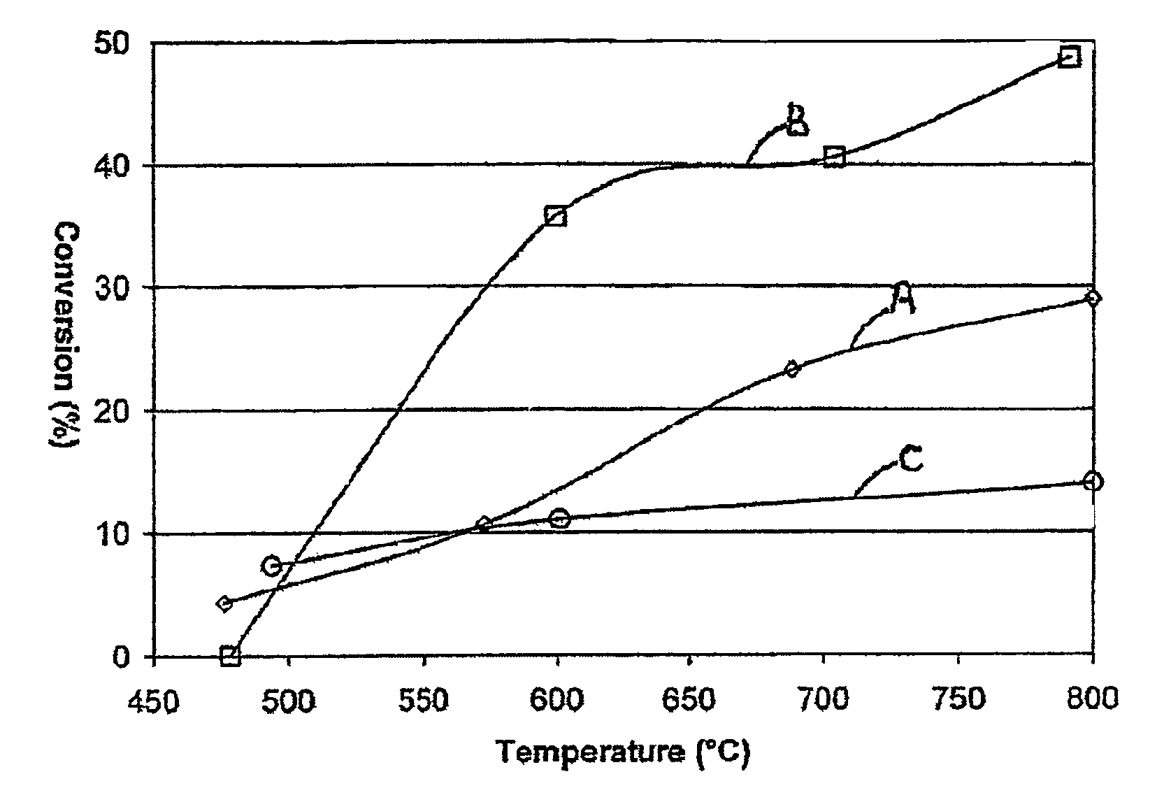
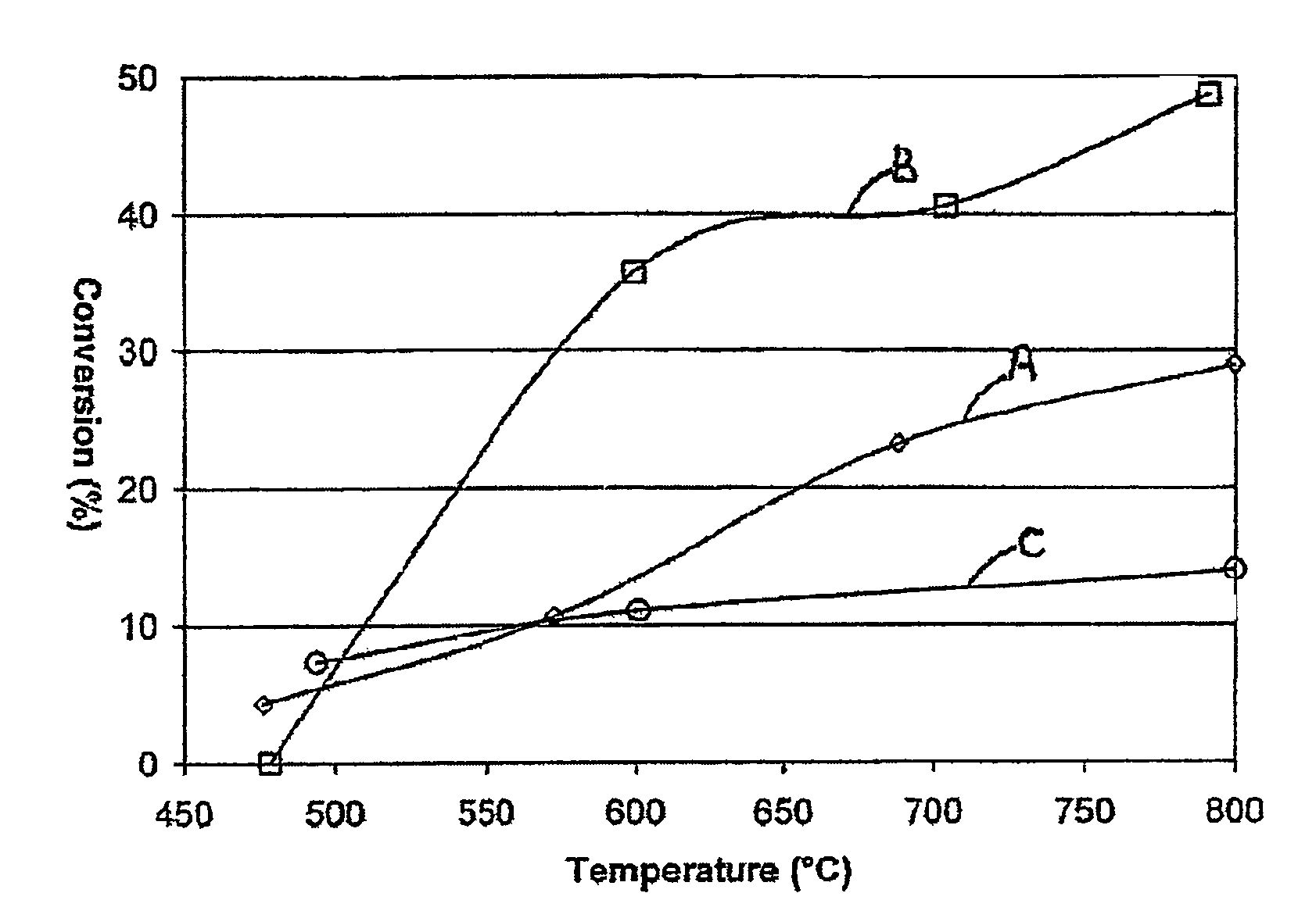
[0060]A large number of tests were performed in a high throughput parallel reactor on a variety of metal or metal oxide catalysts carried on a variety of commercially available and proprietary oxidic supports, including mixed oxide supports, and made in conventional manner. Testing for N2O decomposition led to the following conclusions:[0061]1. Supported base metal oxide catalysts have low activity, although Ni, preferably Ni on CeO2, was the most active;[0062]2. For PGM catalysts, at equivalent loadings, Pd>Ir>>Ru or Pt;[0063]3. Mixed PGM catalysts offer little to negative benefit over single PGM metal catalysts;[0064]4. Addition of other metals tends to degrade the performance of Rh;[0065]5. The absolute activity of Rh catalysts is support dependent, with alumina or ceria / alumina / zirconia being the best; and[0066]6. At “high” loadings (>5%), Pt and Ru show reasonable activity.

example 3

[0067]The highest activity N20 destruction catalyst from Example 2, 0.5% Rh on alumina, was compared with a LaCeCo oxide catalyst prepared according to WO 98 / 28073, in a representative gas comprising NOx, oxygen and water vapour, at various temperatures, both “fresh” and after hydrothermal aging at 1000° C. in air, to represent a used catalyst. The fresh Rh catalyst showed the best performance from about 500° C., reaching 100% conversion at about 800° C., however, even the aged LaCeCo oxide catalyst showed greater than 90% conversion at 900° C.


PUM

PropertyMeasurementUnit
temperatureaaaaaaaaaa
temperaturesaaaaaaaaaa

Abstract

A catalyst charge for ammonia oxidation, including the Andrussow process, comprises a first stage ammonia oxidation catalyst capable of oxidizing 20 to 99% of designed ammonia throughput, to produce a first stage product gas comprising unreacted ammonia, oxygen and nitrogen oxides, and a second stage ammonia oxidation catalyst capable of completing the oxidation of unreacted ammonia. Low levels of nitrous oxide are produced an extended campaign lengths may be seen.

Description

[0001]This application is the U.S. National Phase application of PCT International Application No. PCT / GB2004 / 001783, filed Apr. 27, 2004, and claims priority of British Patent Application No. 0309747.4, filed Apr. 29, 2003, and British Patent Application No. 0315643.7, filed Jul. 4, 2003.FIELD OF THE INVENTION[0002]The present invention concerns an improved catalyst charge design, suitable for an ammonia oxidation process. More particularly, it concerns a two- or multi-stage catalyst charge, which is believed to offer technical and economic advantages.BACKGROUND OF THE INVENTION[0003]The oxidation of ammonia using air to form nitric oxide for nitric acid production, for nitrate fertilisers or explosives, has been established since the early 20th Century (the Ostwald process), and is in widespread use across the world. The established process uses a platinum or platinum alloy gauze as catalyst for the reaction of ammonia with the oxygen in air. The Andrussow process for the producti...

Claims


Application Information

Patent Timeline
Patent Type & Authority Patents(United States)
IPC IPC(8): C01B21/26B01J23/40B01J23/46B01J23/63B01J23/83B01J35/00C01C3/02
CPCB01J23/40B01J23/83B01J35/0006C01B21/265C01C3/0216B01J23/464B01J23/63B01J35/19C01B21/26
Inventor AXON, SEAN ALEXANDERCOUPLAND, DUNCAN ROYHORNER, BRIAN THOMASRIDLAND, JOHNWISHART, IAN CARMICHAEL
Owner JOHNSON MATTHEY PLC
Why Eureka
Try Eureka