

Wet flue gas denitration technique for nitrite recovery
A nitrite and flue gas technology, applied in the field of wet flue gas denitrification process, can solve the problems of affecting economy, high waste water treatment cost, unfavorable resource recovery and utilization, etc., and achieve simple process system structure, low investment and operation cost , Realize the effect of resource utilization
- Summary
- Abstract
- Description
- Claims
- Application Information
AI Technical Summary
Problems solved by technology
Method used
Image

Examples
Embodiment 1
[0041] Example 1: Ozone oxidizes NO combined with calcium hydroxide to absorb denitrification and recover calcium nitrite
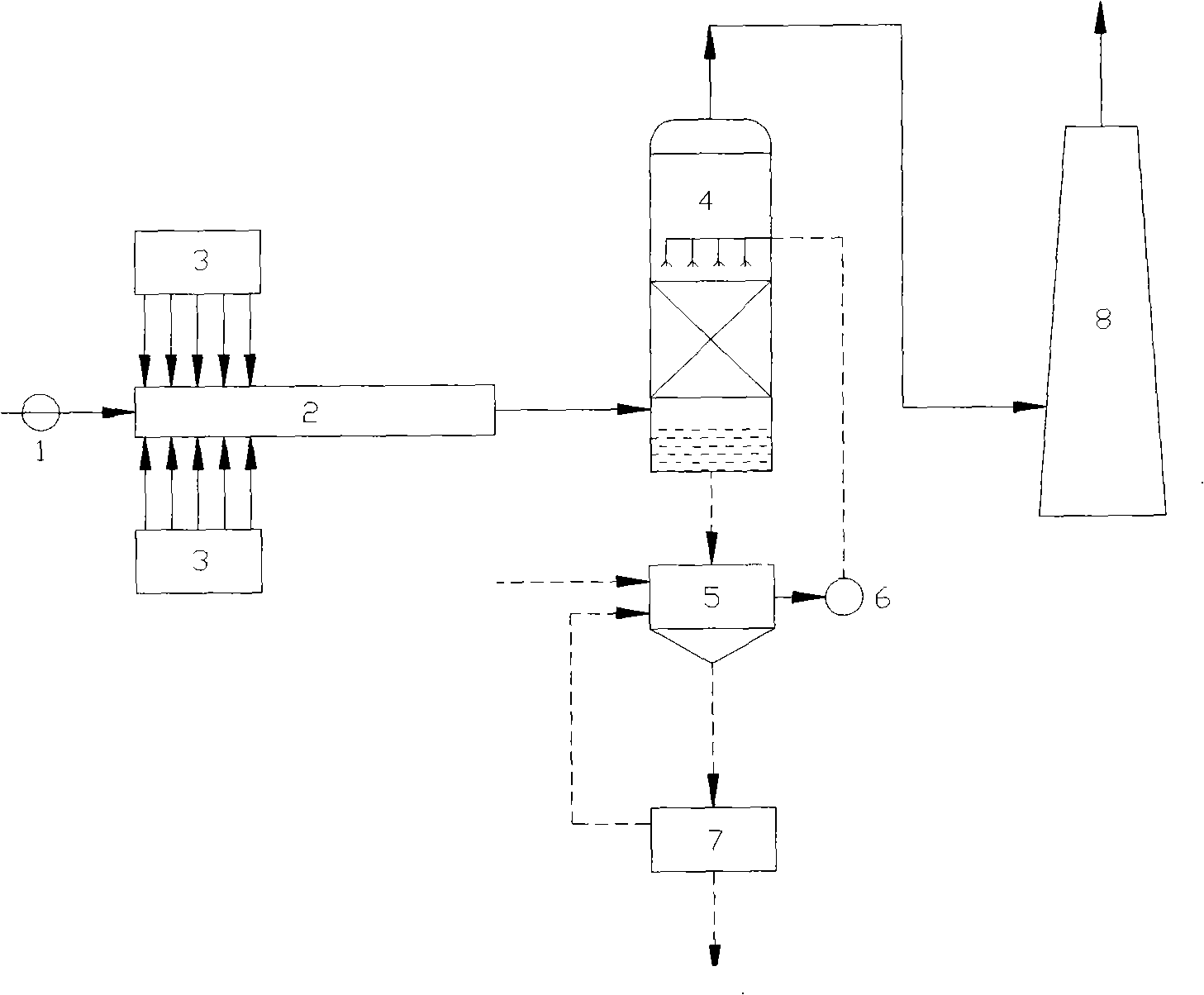
[0042] After the air is dried and purified, it is sent to the oxygen generator, and the generated oxygen is sent to the ozone generator to prepare high-concentration ozone, which is sprayed into the oxidation reaction device. The reaction temperature is 80°C, and the reaction time is controlled to be at least 0.2s. The amount of ozone sent is based on the measured NO concentration in the flue gas, according to the O 3 / NO molar ratio is about 0.4 and dynamically adjusted to keep NO x The degree of oxidation is about 40%. The oxidized flue gas enters the absorption tower, and the absorbent is calcium hydroxide slurry with a concentration of 20%. The absorbent is recycled, and the pH value of the absorbent in the control system is 9. After the reaction, the slurry is discharged, concentrated by heating and evaporation, then cooled and crystallized, and ce...
Embodiment 2
[0043] Example 2: Activate hydrogen peroxide to oxidize NO at high temperature, then use sodium hydroxide to absorb and denitrate, and recover sodium nitrite
[0044] Air is used as the atomizing medium, and 50% hydrogen peroxide solution is thermally activated and then sprayed into the gas-phase oxidation reactor. The activation temperature is about 500°C, and the reaction time is controlled to be at least 0.2s. h 2 o 2 The feeding amount is based on the measured NO concentration in the flue gas, according to the H 2 o 2 / NO molar ratio is about 0.4 ~ 0.8 dynamically adjusted to keep NO x The degree of oxidation is about 40%. The oxidized flue gas enters the absorption tower, and the absorbent is sodium hydroxide solution with a concentration of 10%. The absorbent is recycled, and the reacted absorbent is concentrated by heating and evaporation, then cooled and crystallized, and centrifuged to obtain the sodium nitrite crystal product.
Embodiment 3
[0045] Example 3: UV activating hydrogen peroxide to oxidize NO, then using calcium hydroxide to absorb and denitrify, and recovering calcium nitrite
[0046] Using air as the atomization medium, photoactivate 70% hydrogen peroxide solution and spray it into the gas-phase oxidation reactor. A low-pressure mercury lamp with a wavelength of 200-320nm is installed in the activation reactor. The temperature of the activation reactor is 95°C to control the reaction. The time is at least 0.2s. h 2 o 2 The feeding amount is based on the measured NO concentration in the flue gas, according to the H 2 o 2 / NO molar ratio is about 0.4 ~ 0.8 dynamically adjusted to keep NO x The degree of oxidation is about 40%. The oxidized flue gas enters the absorption tower, and the absorbent is calcium hydroxide solution with a concentration of 20%. The absorbent is recycled, and the pH value of the absorbent in the control system is 9. After the reaction, the slurry is discharged, concentrate...
PUM
 Abstract
Description
Claims
Application Information