Implantable microneedle tip electrode and manufacturing method thereof

A manufacturing method and micro-needle tip technology, applied in the direction of electrodes, internal electrodes, circuits, etc., can solve the problems of large tissue damage, difficult to control the size, high process cost, etc., to reduce tissue damage, suitable for long-term implantation, implantation safety convenient effect

Active Publication Date: 2011-12-21
析芒(宁波)生物微系统有限公司
View PDF5 Cites 5 Cited by
  • Summary
  • Abstract
  • Description
  • Claims
  • Application Information

AI Technical Summary

Problems solved by technology

Due to different processing techniques, the Utah needle-tip electrode is a vertical needle tip, and the Michigan needle-tip electrode is a horizontal needle tip, which has the following disadvantages: 1. Both use brittle and bioincompatible silicon materials as mechanical supports, and the microelectrode itself is easily damaged and damaged. It will cause further damage to the tissue and is not suitable for long-term implantation in vivo; 2. The size of the needle tip is limited by the process. The longest Utah needle tip can only be 1.5mm, and the thickness of the Michigan needle tip does not exceed 15μm; 3. Each Utah needle tip has a There is only one stimulation point, and only the same depth of nerve electrical stimulation or recording can be performed

Method used


Image

  • Implantable microneedle tip electrode and manufacturing method thereof
  • Implantable microneedle tip electrode and manufacturing method thereof
  • Implantable microneedle tip electrode and manufacturing method thereof

Examples


Example Embodiment

[0041] The specific embodiments of the present invention will be described in further detail below in conjunction with the drawings and embodiments. The following examples are used to illustrate the present invention, but not to limit the scope of the present invention.

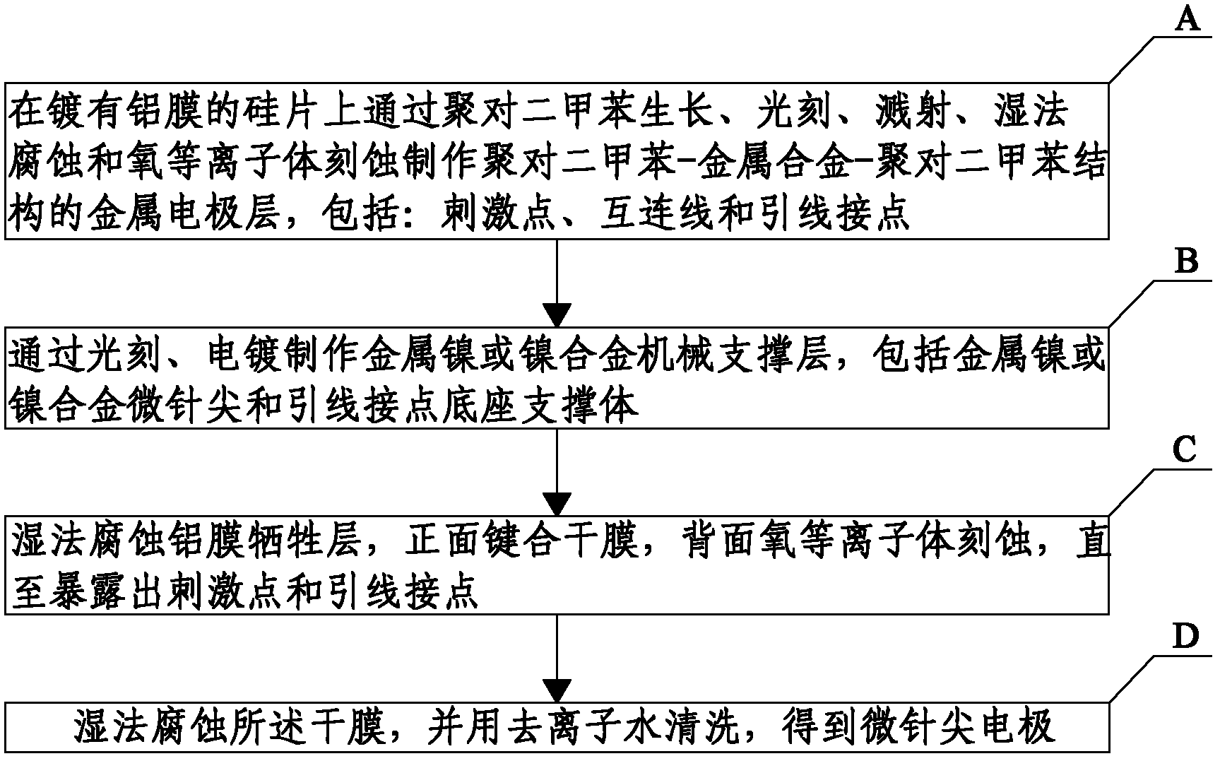
[0042] Such as figure 1 As shown, the manufacturing method of the implantable micro-needle tip electrode of the present invention includes the following steps:

[0043] A: A metal electrode with a parylene-metal alloy-parylene structure is made by parylene growth, photolithography, sputtering, wet etching and oxygen plasma etching on a silicon wafer coated with aluminum film Layers, including: stimulation points, interconnection lines and lead contacts;

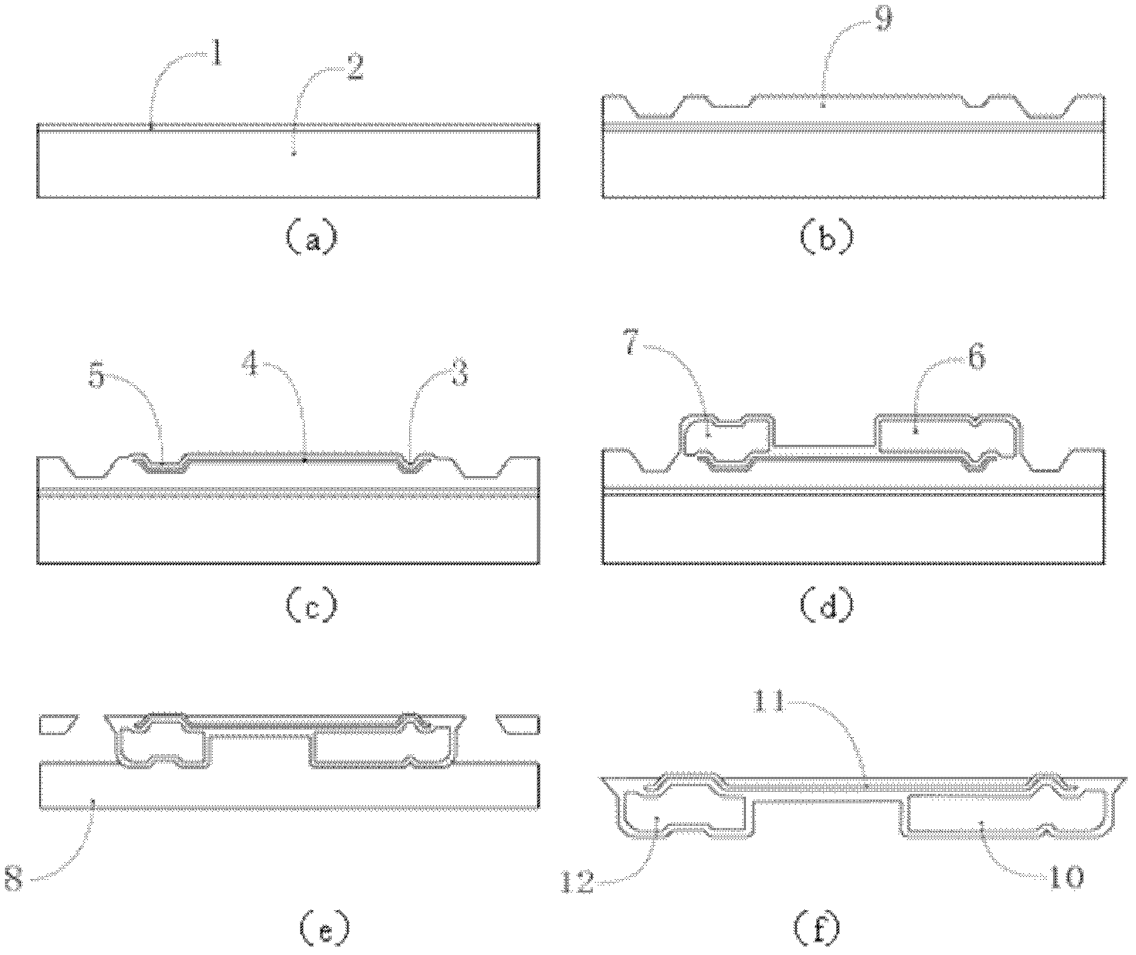
[0044] This step can be achieved by the following method.

[0045] A1: Use silicon wafer 2 and evaporate aluminum film 1 to make an aluminum sacrificial layer, where the thickness of aluminum film 1 can be about 1 μm, such as figure 2 (a);

[0046] A2: Deposit para...


PUM


Abstract

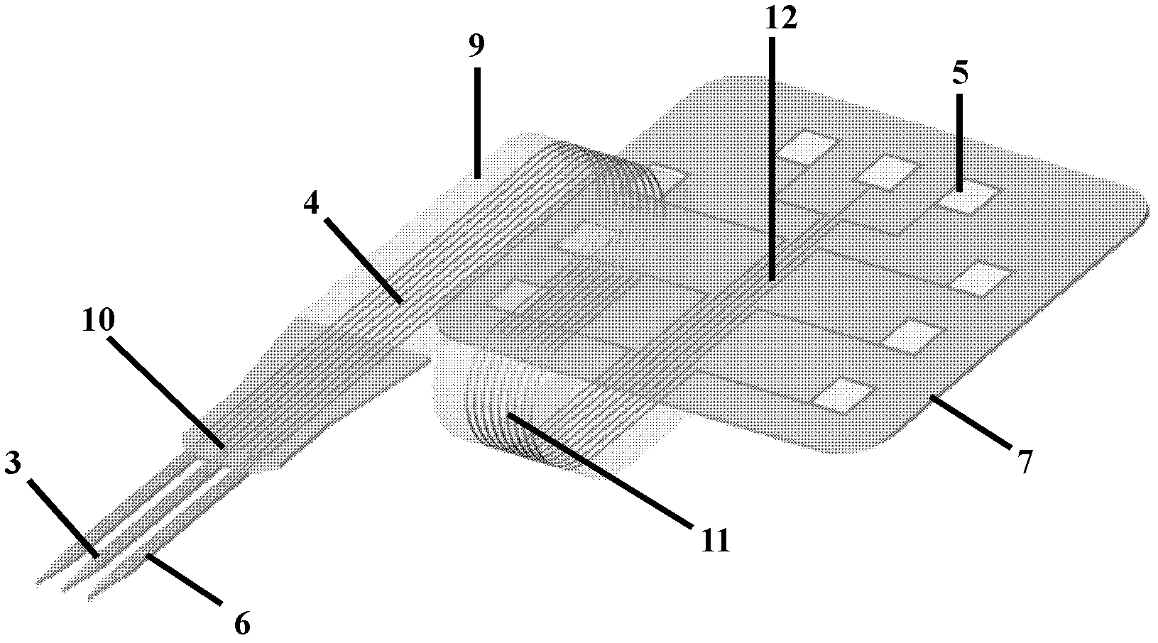
The invention discloses an embedded micro-pinpoint electrode and a manufacturing method thereof, which relates to the technical field of micro-electronic mechanical systems and embedded micro-electrodes. The method comprises the following steps: A: manufacturing a metal electrode layer of a parylene-metal alloy-parylene structure on a silicon piece (2) coated with an aluminum film (1), wherein the metal electrode layer comprises an exciting point (3), an interconnection line (4) and a lead connecting line (5); B: manufacturing a nickel metal or nickel alloy mechanical supporting layer by photoetching and plating, wherein the mechanical supporting layer comprises a nickel metal or nickel alloy micro pinpoint (6) and a base supporting body of the lead connecting point (7); C: eroding an aluminum film victimization layer by a wetting method; bonding a dry film (8) on a front surface; etching an oxygen plasma on a back surface until an exciting point and a lead connecting point are exposed; and D: eroding the dry file by the wetting method and cleaning by using deionized water to obtain the micro-pinpoint electrode. The invention has the characteristics of high mechanical performance,good biological compatibility, convenient embedding, light damage to tissue, accurate and controllable size, high sensibility and high reliability.

Description

technical field [0001] The invention relates to the technical field of micro-electromechanical systems and implanted micro-electrodes, in particular to an implanted micro-needle electrode and a manufacturing method thereof. Background technique [0002] Implantable microneedle electrode is a kind of nerve interface used to electrically stimulate nerves and record nerve electrical signals. Compared with planar microelectrodes, the advantage is that the stimulation point can penetrate deep into the tissue, form good contact with nerve cells, and improve the efficiency of electrical stimulation. efficiency or the signal-to-noise ratio of the acquired signal. [0003] Implantable micro-needle-tip electrodes need strong toughness and hardness, easy to penetrate into the tissue without damaging the tissue structure, and resistant to electrochemical reaction corrosion in the tissue. More importantly, they need good biocompatibility in order to be stable for a long time Stimulate t...

Claims


Application Information

Patent Timeline
IPC IPC(8): G03F7/00G03F7/26G03F7/039A61B5/04A61N1/05B81C1/00
Inventor 李志宏余怀强王朔王玮
Owner 析芒(宁波)生物微系统有限公司
Why Eureka
Try Eureka