
Gradient micro-droplet array forming method based on sequential injection and microfluidic technology

A microfluidic technology and sequential injection technology, applied in the field of gradient micro-droplet array formation, can solve the problems of sample waste, limited application, low reproducibility of screening system, etc., and achieve simple device and principle and high degree of automation , the effect of saving experimental cost

Active Publication Date: 2015-08-19
ZHEJIANG UNIV
View PDF3 Cites 14 Cited by
  • Summary
  • Abstract
  • Description
  • Claims
  • Application Information

AI Technical Summary

Problems solved by technology

However, the above-mentioned methods all have relatively large limitations, which are mainly reflected in: 1) The continuous flow system is more suitable for screening systems at the molecular level, such as enzyme inhibition screening, etc., but it is difficult to apply to screening systems that require static culture, such as cell Horizontal screening and screening of protein crystallization conditions; 2) The detection of continuous flow systems mainly relies on end-point detection methods such as laser-induced fluorescence, which limits its application in screening systems that require real-time monitoring and imaging analysis; 3) In current systems, enzymes and Reagent solutions such as substrates are continuously injected into the reaction channel, forming a large number of empty reaction droplets, resulting in additional waste of samples; 4) In the continuous flow droplet system, the formation of concentration gradients and the generation of droplets are easily affected by liquid viscosity, temperature Influenced by other factors, the reproducibility of the screening system is not high

Method used


Image

  • Gradient micro-droplet array forming method based on sequential injection and microfluidic technology
  • Gradient micro-droplet array forming method based on sequential injection and microfluidic technology
  • Gradient micro-droplet array forming method based on sequential injection and microfluidic technology

Examples


Embodiment 1

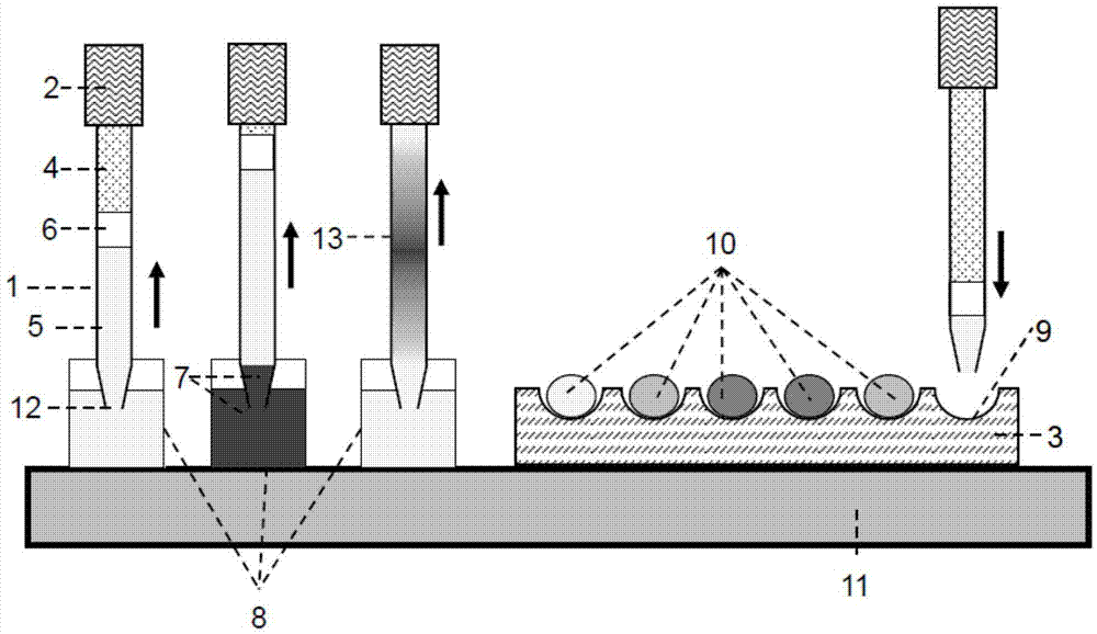
[0050] figure 1 It is a schematic diagram of the formation method of gradient micro-droplet array based on sequential injection and microfluidic droplet technology. The specific operation process is as follows: use the capillary 1 as a sampling probe, and connect its tail to the liquid driving system 2 . The sampling port 12 of the capillary 1 is sharpened to reduce cross-contamination during sampling. The inner wall of the capillary 1 and the outer wall of the sampling port 12 are treated with fluorosilanization to prevent the adsorption of samples / reagents on their surfaces. The liquid with low thermal expansion coefficient is filled in the capillary 1 as the carrier stream 4, and the air bubbles in the capillary 1 and the liquid driving system 2 are completely removed. An oil phase 6 immiscible with the sample / diluent is introduced into the sampling port 12 of the capillary 1 to separate the carrier stream 4 and the diluent 5 . The storage tube of the sample / reagent 7 an...

Embodiment 2

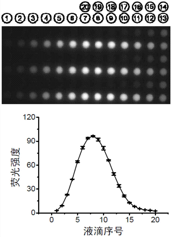
[0052] figure 2 is based on figure 1In the sequential injection gradient method, the micro-droplet array fluorescence pictures and corresponding curves generated by using sodium fluorescein as a model sample. A syringe pump is used as the liquid driving device 2, and a layer of mineral oil is covered on the microwell array chip 3 to avoid the evaporation of micro samples in the microwells. Start the syringe pump, first draw 120 nanoliters of 50 mmol per liter borax buffer as a diluent in capillary 1, then draw 20 nanoliters of 1 mmol per liter sodium fluorescein sample, and then draw 60 nanoliters of Borax buffer. During the extraction process, sodium fluorescein diffuses in the borax buffer to form a sample zone. Then, the sodium fluorescein sample zone in the capillary 1 was spotted onto the microwell array chip 3 to form a droplet array 10 , each droplet had a volume of 9 nanoliters, and a total of 20 droplets were formed. Repeat the above steps 3 times to generate a t...

Embodiment 3

[0054] image 3 is to use figure 1 Schematic diagram of the operation process of quantitative high-throughput protein crystallization condition screening by the sequential injection gradient micro-droplet array method. Firstly, a layer of mineral oil is covered on the microwell array chip 3 to avoid the evaporation of trace samples in the microwells. A certain volume of precipitant solution 14 is extracted in the storage tube 8 of the precipitant solution, and then pushed out into the microwells 9, and the volume of the precipitant droplet in each well is 2 nanoliters. according to figure 1 In the described method, 50 nanoliters of protein buffer solution, 20 nanoliters of protein solution 15 and 50 nanoliters of protein buffer solution are sequentially extracted in the capillary 1, and the protein solution 15 diffuses in the capillary to form a protein zone with a concentration gradient. Inject 2 nanoliters of the protein zone solution into the precipitant solution in each...


PUM


Abstract

The invention discloses a gradient micro-droplet array forming method based on sequential injection and microfluidic technology. The gradient micro-droplet array forming method comprises following steps: step 1, one of a diluent and a sample I is taken using a capillary tube; step 2, the other one of the diluent and the sample I is taken using the capillary tube, and direct contact of the diluent with the sample I is ensured so as to form a sample zone belt with axial concentration gradient; and step 3, the sample zone belt is injected into certain areas of a microporous array chip via the capillary tube so as to obtain sample droplet array with different concentration on the microporous array chip. Advantages of the gradient micro-droplet array forming method are that: concentration gradient generation throughput is high, concentration information is abundant, automatic degree is high; sample consumption is low, and devices and principles are simple. The gradient micro-droplet array forming method can be used for biochemical analysis and screening such as high throughput drug screening, compound toxicity determination, protein crystallization condition screening, catalyst screening, and enzyme dynamic analysis.

Description

technical field [0001] The invention relates to the field of microfluidic droplet analysis and screening, in particular to a method for forming a gradient microdroplet array based on sequential injection and microfluidic droplet technology. Background technique [0002] High Throughput Screening (HTS) uses computer and automated robot technology to complete the complex liquid manipulation, high-sensitivity detection and data processing required for biochemical analysis, and can achieve an analysis throughput of more than 10,000 samples / day. Due to its powerful screening and analysis functions, the application range of high-throughput screening technology has expanded from new drug research and development to biology, medicine, chemistry and other scientific fields, such as structural biology, combinatorial chemistry, synthetic biology, clinical screening As well as occasions where large-scale biochemical analysis experiments are required in various omics studies, it has beco...

Claims


Application Information

Patent Timeline
IPC IPC(8): G01N1/28B01L3/00
Inventor 方群祝莹魏岩
Owner ZHEJIANG UNIV
Learn More