
Zero emission treatment method of high-salinity wastewater

A treatment method, high salt content technology, applied in water/sewage treatment, heating water/sewage treatment, multi-stage water/sewage treatment, etc., can solve the problems of increased energy consumption, fouling of membrane elements and organic fouling, and reliability Low-level problems, to achieve the effect of reducing processing costs, reducing consumption, and reducing energy consumption

Active Publication Date: 2016-04-20
BGT GRP CO LTD
View PDF4 Cites 21 Cited by
  • Summary
  • Abstract
  • Description
  • Claims
  • Application Information

AI Technical Summary

Problems solved by technology

[0004] The use of reverse osmosis membrane to treat wastewater has developed rapidly, but the problems of this technology in the treatment of complex wastewater have become increasingly prominent. The main problems are manifested in two aspects: First, the desalination rate that can be achieved by reverse osmosis membrane elements is 98 %, more than 98% of the salt and impurities in the wastewater are intercepted and separated in the concentrated water generated by the system, while the recycling rate of the wastewater by the reverse osmosis membrane method can only reach about 75%, and there are still 25% of the concentrated water that cannot be used. need direct discharge
The high desalination rate of reverse osmosis membrane elements makes this part of the concentrated water contain a large amount of calcium ions, magnesium ions, heavy metal ions, silicon ions, colloids and organic pollutants, etc. If this part of the concentrated water is discharged directly, it will definitely pollute the environment
Direct use of multiple effects for evaporation and crystallization of concentrated water will consume a large amount of steam, resulting in increased wastewater treatment costs
Second, complex salty waste water concentrated by low-pressure, medium-pressure and high-pressure reverse osmosis, when treated by reverse osmosis equipment, organic pollutants and saturated inorganic salts are prone to fouling on the membrane surface, resulting in increased separation difficulty and low energy efficiency. Increased consumption, poor economy, low reliability
The treatment method provided by this patent adopts the integrated process of high-density clarification tank process, filtration process, nanofiltration treatment process and reverse osmosis treatment process. Although the wastewater can meet the requirement of zero discharge through the above process, the method provided by this patent There are at least the following defects: (1) the treatment method is only aimed at low-concentration organic matter reverse osmosis concentrated water, and the treatment effect on high-salt wastewater containing refractory organic matter is not obvious; (2) the treated concentrated water is easy to make the Scaling and organic fouling of the membrane elements affect the recovery rate of wastewater; (3) the patent lacks further reduction measures for wastewater, resulting in a large amount of concentrated water entering the evaporation and crystallization device, and a phase change process occurs when the water is evaporated. High energy consumption during crystallization and increased processing costs

Method used


Image

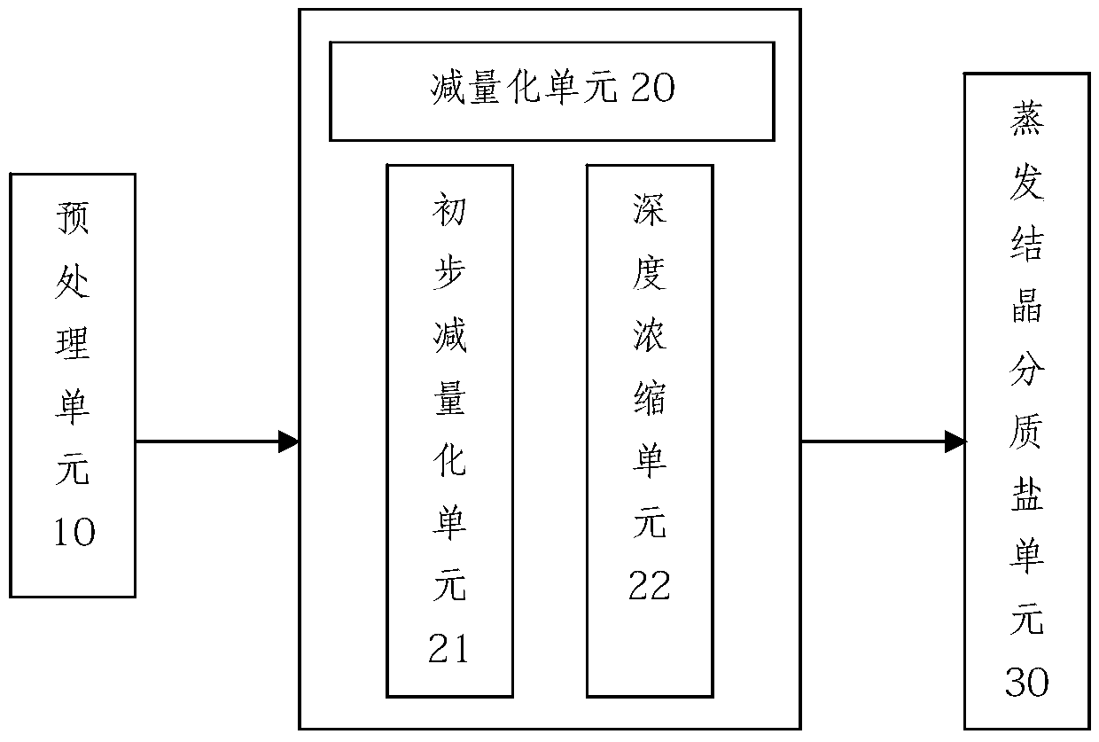
  • Zero emission treatment method of high-salinity wastewater
  • Zero emission treatment method of high-salinity wastewater
  • Zero emission treatment method of high-salinity wastewater

Examples


Embodiment 1

[0064] Take the structure of the one-stage electrically driven ion membrane device 224 and the two-stage electrically driven ion membrane device 226 used in the present invention as an example.

[0065] The first-stage electrically driven ion membrane device 224 and the second-stage electrically driven ion membrane device 226 include an anode and a cathode arranged at intervals. Between the anode and the cathode are regularly arranged a plurality of membrane pairs composed of positive membranes, negative membranes and separators. The positive and negative membranes are homogeneous membranes with low membrane resistance and high performance. Between the two membranes is a separator with uniform flow state. The power supply of the first-level electric-driven ion membrane device 224 and the second-level electric-drive ion membrane device 226 adopts a high-frequency direct current power supply with positive and negative polarity automatic switching, and uses a digital program to ...

Embodiment 2

[0069] Take the wastewater pretreatment process as an example.

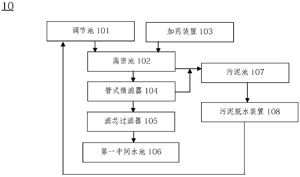
[0070] Such as figure 2 As shown, the device of the pretreatment process of wastewater at least includes a regulating tank 101, a high-density tank 102, a dosing device 103, a tubular microfilter 104, a cartridge filter 105, a first intermediate tank 106, a sludge tank 107 and a sludge dewatering device 108.

[0071]The regulating pool 101 regulates the homogeneity and equalization of the wastewater sent by each pipeline. The homogeneous and uniformly regulated waste water is sent into the high-density pool 102 through a lift pump. Add lime or sodium hydroxide, sodium carbonate, polyaluminum chloride and polyacrylamide to the wastewater in the high-density pool 102 through the dosing device 103 . Preferably, the amount of chemical added should not be too large, and it needs to be adjusted accordingly according to the actual water quality, otherwise it will easily cause membrane pollution and affect the servic...

Embodiment 3

[0074] Take waste water reduction treatment process as an example.

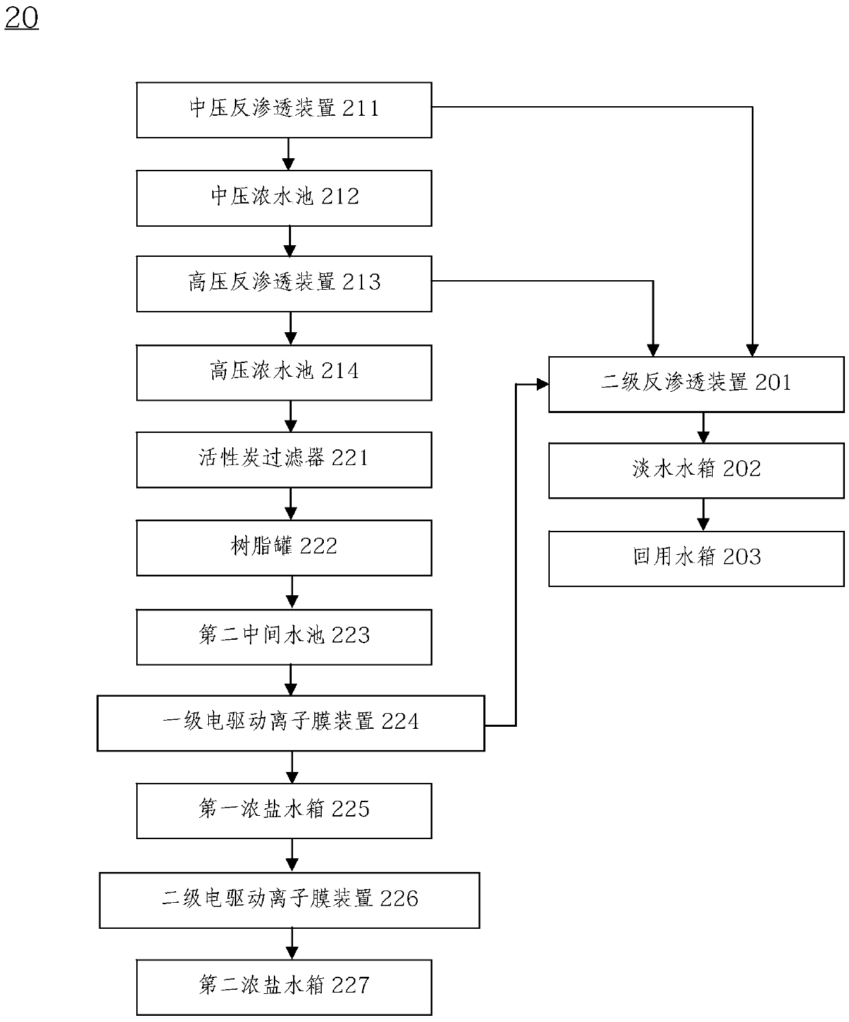
[0075] Wastewater reduction process includes primary reduction process and deep concentration process. Such as image 3 As shown, the devices of the preliminary reduction process include at least a medium-pressure reverse osmosis device 211 , a medium-pressure concentrated water tank 212 , a high-pressure reverse osmosis device 213 and a high-pressure concentrated water tank 214 . The device of the deep concentration process at least includes an activated carbon filter 221, a resin tank 222, a second intermediate pool 223, a first-stage electric drive ion membrane device 224, a first concentrated brine tank 225, a second electric drive ion membrane device 226 and a second concentration Brine tank 227 . The devices of the reduction process also include a secondary reverse osmosis device 201 , a fresh water tank 202 and a recycled water tank 203 .

[0076] The pretreated waste water collected in the first in...


PUM

PropertyMeasurementUnit
sizeaaaaaaaaaa
thicknessaaaaaaaaaa

Abstract

The invention relates to a zero emission treatment method of high-salinity wastewater. The method comprises a pre-treatment technology of wastewater, a reduction technology of the wastewater and an evaporative crystallization technology of the high-salinity wastewater, wherein the pre-treatment technology is implemented as follows: a flocculation and / or sedimentation chemical agent is added, heavy metal ions, hard ions and organic substances in the high-salinity wastewater are removed from a chemical reactor, and the pH of the wastewater is adjusted until the wastewater is alkaline; the reduction technology is implemented as follows: the pretreated wastewater is subjected to preliminary reduction treatment through a medium-pressure reverse osmosis device and a high-pressure reverse osmosis device to form high-pressure reverse osmosis concentrated water, the high-pressure reverse osmosis concentrated water is subjected to deep concentration treatment through a primary electric drive ionic membrane device and a secondary electric drive ionic membrane device, high-salinity concentrated water is obtained through concentration, and producing water in the reduction process is recovered to a recycling water tank; the evaporative crystallization technology is implemented as follows: salts in the high-salinity concentrated water are recovered under the negative pressure or micro-positive pressure condition through a nitrate evaporative crystallization device and a salt evaporative crystallization device, and sodium sulfate and sodium chloride are formed.

Description

technical field [0001] The invention relates to the technical field of industrial wastewater treatment, in particular to a zero-discharge treatment method for high-salt wastewater. Background technique [0002] In recent years, with the rapid development of petrochemical, electric power, metallurgy, coal chemical industry and other industries, the amount of wastewater containing complex components produced in the process of industrial production has also increased year by year. The problem of how to dispose and utilize these wastewater containing complex components has been widely Pay attention to. Especially in areas where water resources are scarce, how to make good use of this part of wastewater and realize zero discharge of wastewater is of great significance for protecting the surrounding environment and natural water bodies on which we live, further improving the comprehensive utilization efficiency of water resources, and alleviating the tension of water resources. ....

Claims


Application Information

Patent Timeline
Patent Type & Authority Applications(China)
IPC IPC(8): C02F9/10
CPCC02F1/001C02F1/04C02F1/441C02F1/444C02F1/4698C02F1/52C02F9/00
Inventor 权秋红张建飞石维平元西方
Owner BGT GRP CO LTD
Learn More