Marine anti-corrosion anti-fouling composite coating and preparation method thereof

A composite coating and anti-fouling technology, which is applied in the direction of coating, metal material coating process, superimposed layer plating, etc., can solve the problems of low bonding strength and the insulation of the ceramic layer needs to be improved, and achieve good bonding strength, Excellent long-term corrosion protection effect and close thermal expansion coefficient

Active Publication Date: 2018-06-15
SHANGHAI INST OF CERAMIC CHEM & TECH CHINESE ACAD OF SCI +1
View PDF3 Cites 7 Cited by
  • Summary
  • Abstract
  • Description
  • Claims
  • Application Information

AI Technical Summary

Problems solved by technology

At present, some researchers have designed oxide ceramic layers such as alumina, alumina and titanium oxide composites between the substrate and the copper alloy coating, but the ceramic layer must not only meet the insulation function, but also withstand the long-term corrosion of seawater, making the oxidation The bonding strength of oxide ceramic layers such as aluminum, aluminum oxide and titanium oxide composites to the substrate is low, and the insulation of the ceramic layer also needs to be improved

Method used


Image

  • Marine anti-corrosion anti-fouling composite coating and preparation method thereof
  • Marine anti-corrosion anti-fouling composite coating and preparation method thereof
  • Marine anti-corrosion anti-fouling composite coating and preparation method thereof

Examples


Embodiment 1

[0045] (1) The metal substrate is a 304 stainless steel rectangular test piece with a size of 30mm×15mm×1.25mm. Pretreatment of the surface of the metal substrate to be sprayed: sandblasting, ultrasonic cleaning, compressed air drying;

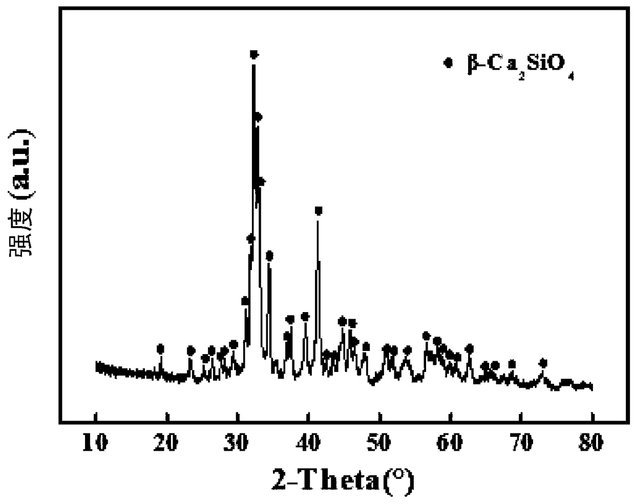
[0046] (2) Atmospheric plasma spraying: The atmospheric plasma spraying process is used to spray a 20 μm NiCr transition layer and a 130 μm dicalcium silicate coating on the surface pretreated metal substrate. Among them, using NiCr powder as raw material, the process parameters of spraying NiCr transition layer are: plasma gas argon gas flow rate 57slpm, plasma gas hydrogen gas flow rate 8slpm, spraying current 600A, voltage 74V, powder feeding tube diameter 1.8mm, spraying distance 120mm, Spraying time is 6 minutes. Using γ-dicalcium silicate powder as raw material, the process parameters of spraying dicalcium silicate coating are: plasma gas argon flow rate 49slpm, plasma gas hydrogen flow rate 9slpm, spraying current 650A, voltage 74V, po...

Embodiment 2

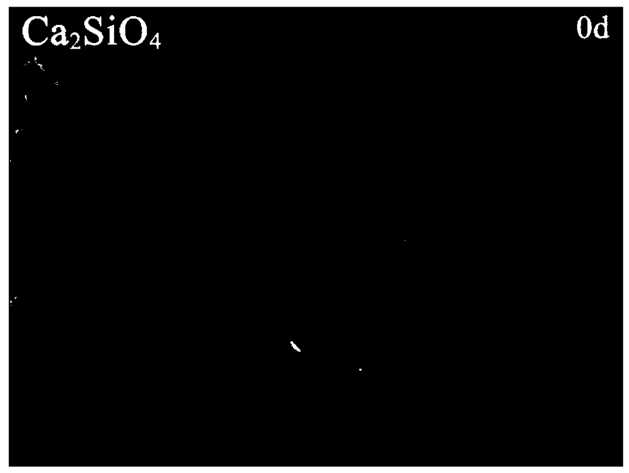
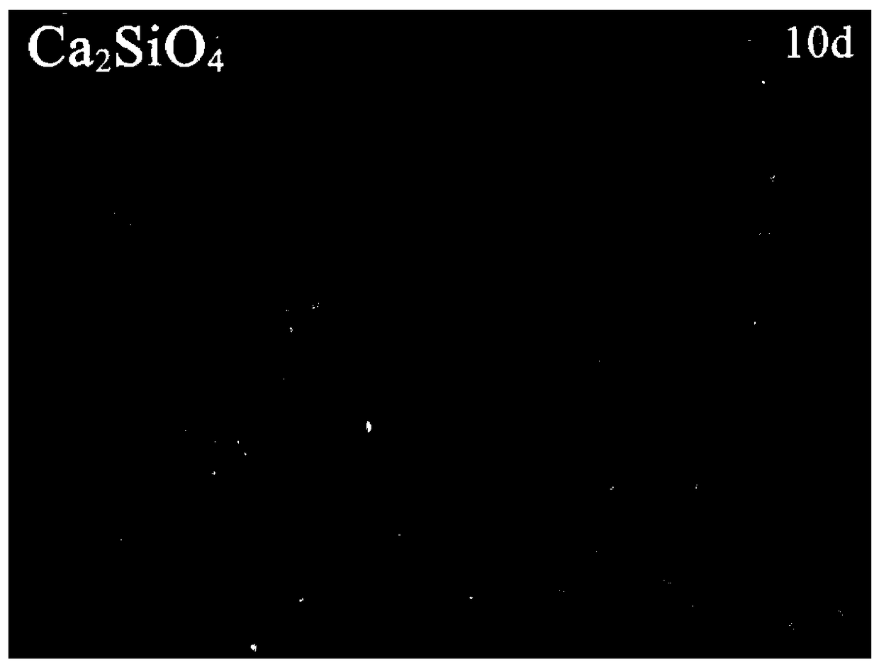
[0048] The sample obtained in Example 1 was soaked in 3.5wt% NaCl solution for 30 days. Figure 2-4 The SEM photos of the cross-section of the sample before and after immersion show that the porosity of the dicalcium silicate coating decreases after immersion, indicating that the coating has self-sealing properties.

Embodiment 3

[0050] The preparation method is the same as in Example 1, except that a 300 μm copper alloy coating is sprayed on the dicalcium silicate coating. Using copper-nickel alloy powder as raw material, the process parameters for spraying copper alloy coating are: plasma gas argon flow rate 57slpm, plasma gas hydrogen flow rate 7slpm, spraying current 580A, voltage 74V, powder feeding tube diameter 1.8mm, spraying distance 130mm , spraying time 25 minutes. The sample prepared in Example 3 was subjected to a salt spray corrosion test, using a sodium chloride solution with a concentration of 5.0 wt%, and at 35±2°C, alternating dry and wet cycles (spray for 24 hours, stop spraying for 24 hours). Figure 5 (a) and (b) are photos of the samples after 100h and 1000h salt spray corrosion respectively. It can be seen from the figure that after 1000 hours of salt spray corrosion, no obvious galvanic corrosion was found in the sample.


PUM

PropertyMeasurementUnit
Thicknessaaaaaaaaaa

Abstract

The invention relates to a marine anti-corrosion anti-fouling composite coating and a preparation method thereof. The composite coating comprises a beta-dicalcium silicate ceramic coating and a copperalloy coating sequentially formed on the surface of a base material. The beta-dicalcium silicate ceramic coating has a self-sealing characteristic at the existence of water and has better long-time corrosion resistance, the metal base material and the copper alloy coating can be effectively isolated, and the occurrence of galvanic corrosion is inhibited.

Description

technical field [0001] The invention relates to a marine anti-corrosion and anti-fouling composite coating and a preparation method thereof, belonging to the technical field of marine protection. Background technique [0002] Seawater is a strong natural corrosive medium, with a salt concentration as high as 3.5%, rich in oxygen, coupled with the impact of waves and sunlight, the marine corrosive environment is extremely harsh. Corrosion is a major cause of damage and obsolescence of all kinds of infrastructure and industrial equipment. At the same time, there are many kinds of sea creatures that endanger ships in the ocean. There are about 2,000 kinds of sea creatures. Sea creatures will cause the surface of the bottom of the ship to be fouled and rough, which will increase the resistance of the boat. will accelerate the corrosion of metals. [0003] At present, the commonly used method to prevent marine biofouling is to apply anti-fouling paint and scrape the bottom of t...

Claims


Application Information

Patent Timeline
IPC IPC(8): C23C4/11C23C4/06C23C4/134
CPCC23C4/06C23C4/11C23C4/134C23C28/321C23C28/345
Inventor 陶顺衍肖媛邵芳赵华玉杨凯倪金星庄寅
Owner SHANGHAI INST OF CERAMIC CHEM & TECH CHINESE ACAD OF SCI
Why Eureka
Try Eureka