Ta-c-based multilayer wear-resistant cutter coating and preparation method thereof

A ta-c, wear-resistant layer technology, applied in the field of tetrahedral amorphous carbon (ta-c) based composite tool coating and its preparation, can solve the problems of easy peeling failure, stress concentration at the interface, etc., to reduce the surface Large particle distribution, reducing the stress concentration of the film base, and the effect of dense and smooth coating surface

Active Publication Date: 2021-04-13
LANZHOU INST OF CHEM PHYSICS CHINESE ACAD OF SCI +1
View PDF10 Cites 0 Cited by
  • Summary
  • Abstract
  • Description
  • Claims
  • Application Information

AI Technical Summary

Problems solved by technology

If the transition layer cannot effectively play the role of bonding, it can cause stress concentration at the interface, and it is easy to peel off and fail during cutting

Method used


Image

  • Ta-c-based multilayer wear-resistant cutter coating and preparation method thereof
  • Ta-c-based multilayer wear-resistant cutter coating and preparation method thereof
  • Ta-c-based multilayer wear-resistant cutter coating and preparation method thereof

Examples


Embodiment 1

[0034] (1) Commercially purchased YG6 tungsten carbide cutters were used as samples (tool material composition, WC: 94wt.%, Co: 6wt.%, hardness HRA89); the samples were ultrasonically cleaned with acetone and absolute ethanol for 20 minutes to remove Surface oil and its oxides;

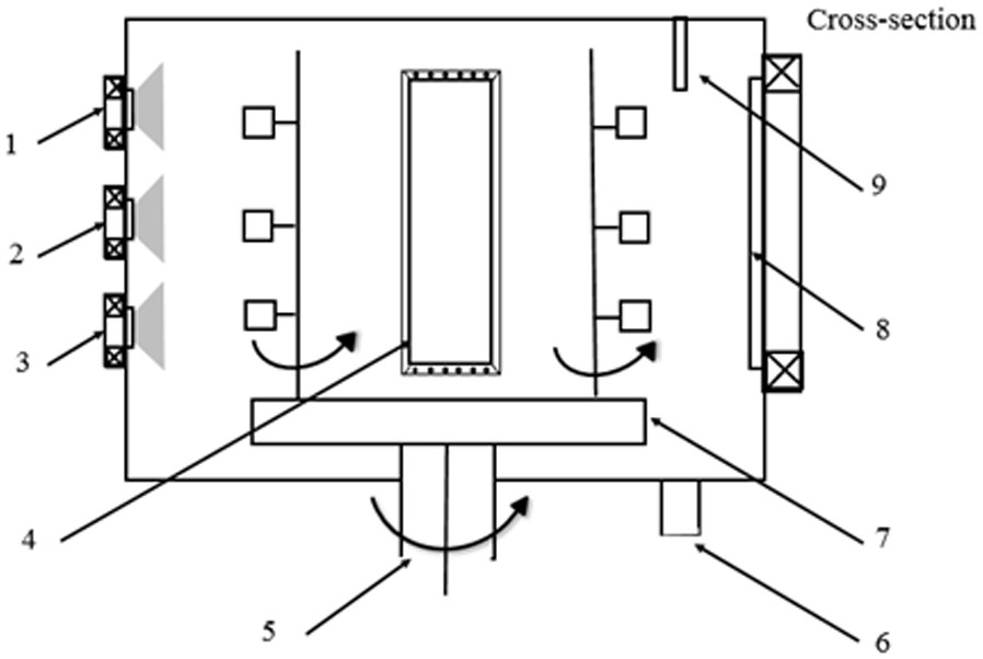
[0035] (2) Use a vacuum cleaner to suck out the impurity particles and fine dust in the vacuum chamber, place the tool holder on the turntable, turn on the vacuum unit, and wait until the vacuum degree of the chamber reaches 3.0×10 -3 At Pa, turn on the magnetron rectangular Cr target, adjust the target power to 200W, and sputter for 10 minutes. This step can eliminate the influence of excess charge in the cavity and contamination of the surface of the fixture, resulting in low film quality;

[0036] (3) Ion etching cleaning of the sample: the tool sample is held on the turntable 7, and the vacuum of the cavity is pumped to 3.0×10 - 3 Pa, the rotation speed of the sample turret is 5rpm / min, and the...

Embodiment 2

[0042] (1) Purchase commercial micro-drills with different grades of cutting diameters, and use petroleum ether, acetone, and absolute ethanol to perform ultrasonic cleaning for 10 minutes respectively. After the ultrasound is over, take out the sample and purge it with dry nitrogen;

[0043] (2) Use a high-power vacuum cleaner to clean the particle impurities, target surface pollutants, and sample turret impurities in the cavity, place the tool holder on the turret, and turn on the vacuum unit until the vacuum degree of the cavity reaches 3.0×10 -3 At Pa, turn on the magnetron rectangular Cr target, adjust the target power to 200W, and sputter for 10 minutes;

[0044] (3) Put the cleaned micro-drill into the clamping set, and vacuum the cavity to a background vacuum of 3.0×10 -3 Below Pa, the temperature is set to 150°C, then 100 sccm / min argon gas is introduced into the cavity, the bias voltage is -300V, and the glow discharge of Ar ions is used to clean for 30 minutes;

...


PUM

PropertyMeasurementUnit
Elastic modulusaaaaaaaaaa
Hardnessaaaaaaaaaa
Hardnessaaaaaaaaaa

Abstract

The invention relates to a magnetron sputtering multi-arc ion plating coupling process deposition cutter coating and particularly discloses a coating which is composed of a metal bonding layer, a ta-c functional wear-resistant layer and a surface diamond-like layer. According to the coating, a metal Cr target and a graphite target material serve as raw materials, and the system structure of a film layer is as follows: (1) a metal Cr layer serves as the bonding layer with a matrix, and provides relatively high bonding strength for the ta-c functional layer at the same time; (2) periodic continuous plating of the ta-c functional layer provides good lubricity in the cutting process; and (3) plating of a surface diamond-like carbon (DLC) film mainly reduces the surface roughness and the pinning effect, and the wear resistance of a film layer system is improved. The ta-c-based multilayer wear-resistant coating prepared through the coupling coating process can remarkably improve the wear resistance and reduce adhesion behaviors in the cutting process, and is particularly suitable for high-precision cutting working conditions.

Description

technical field [0001] The invention relates to a preparation method of a tool coating, in particular to a tetrahedral amorphous carbon (ta-c) based composite tool coating and a preparation method thereof, belonging to the technical field of tool coating preparation. Background technique [0002] With the continuous advancement of modern machining technology, traditional cutting tools have been difficult to meet high-standard processing requirements. When traditional cutting tools are used for high-speed machining, large feed rate, and large depth of material removal, it is easy to cause fast tool wear, low service life, poor machining accuracy, and severe thermal deformation of the tool and parts. The advent of coated tools, which combines high-strength substrates with wear-resistant hard film materials, has played a very important role in the improvement of tool cutting performance and the advancement of processing technology. The hard film not only retains the excellent ...

Claims


Application Information

Patent Timeline
IPC IPC(8): C23C14/02C23C14/06C23C14/32C23C14/35C23C14/50
CPCC23C14/021C23C14/325C23C14/352C23C14/505C23C14/0605C23C14/025
Inventor 王晓波陈庆春李维民赵改青张广安
Owner LANZHOU INST OF CHEM PHYSICS CHINESE ACAD OF SCI
Why Eureka
Try Eureka