Spectrally selective solar absorbing coating and a method for making it

a solar absorber and spectrally selective technology, applied in the direction of superimposed coating process, chromium oxide/hydrate, sensing by electromagnetic radiation, etc., can solve the problems of high demands on accuracy and stability of coating equipment control, complex coating process, reduction of and increase of etc., to achieve high extinction coefficient, low thermal emissivity, and high refractive index

Active Publication Date: 2020-03-10
CHINA BUILDING MATERIALS ACAD
View PDF23 Cites 1 Cited by
  • Summary
  • Abstract
  • Description
  • Claims
  • Application Information

AI Technical Summary

Benefits of technology

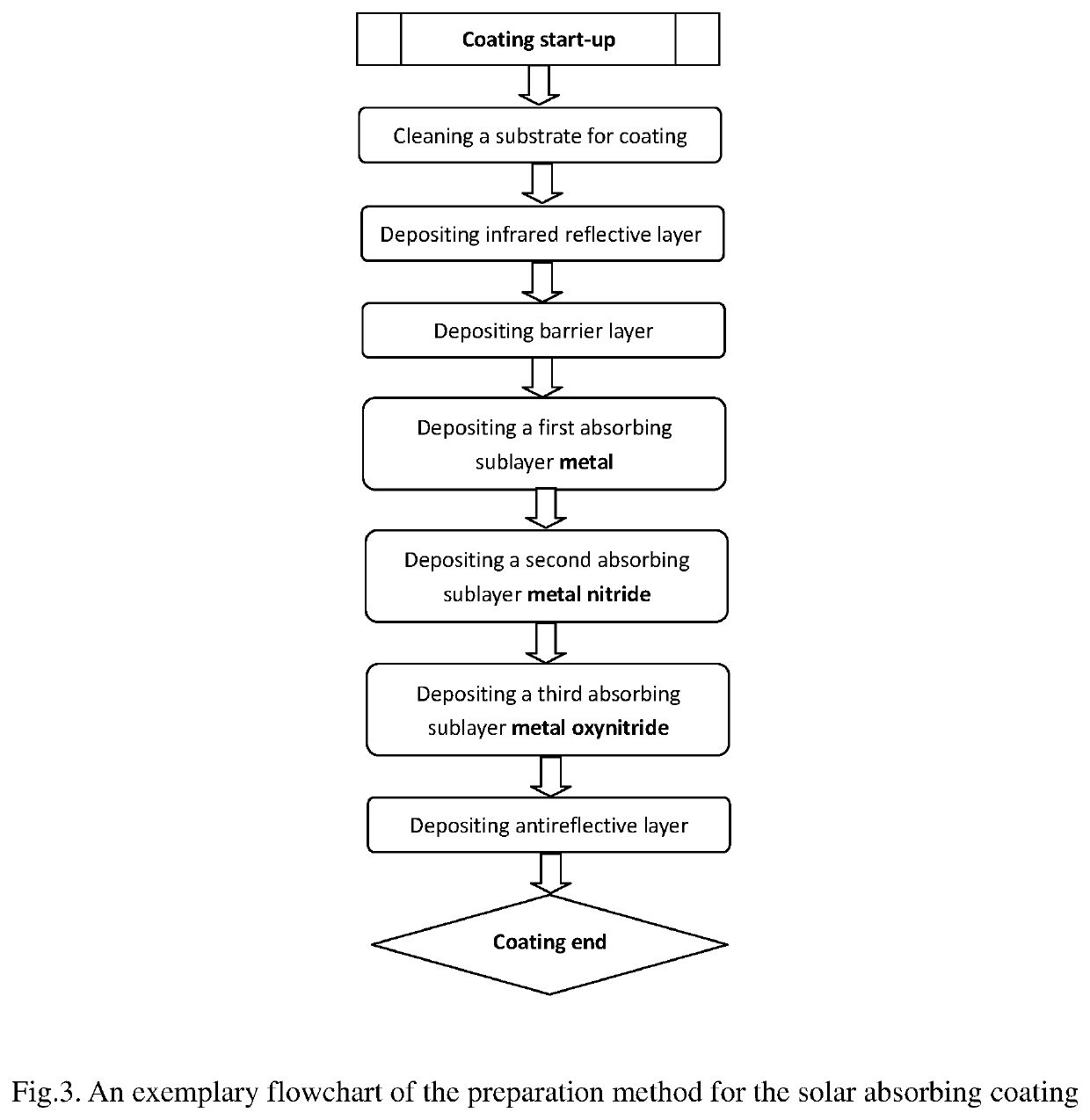
[0012]An object of the present invention is to provide an efficient solar absorbing coating, with a high solar absorptance and most importantly, a low thermal emissivity. Its characteristics are: 1. The coating has excellent spectral selectivity, and can be operated at temperature of 80° C.-250° C. 2. The absorbing layer consists of three absorbing sublayers, which are metal, metal nitride, and metal oxynitride in the order from bottom IR reflective layer to top AR layer. This triple-layer composite absorbing layer makes it possible for the coating to have not only high ratio α / ε, but also good coating adhesion strength and high thermal circle stability. 3. The method of the present invention has simple coating processing, low equipment requirement and high deposition rate, making it suitable for large-scale, low-cost production.
[0036]The second absorbing sublayer CrNx(x=0.9-1.5) is almost transparent to the longer IR wavelengths, therefore, it does not re-radiate and has little impact on the thermal emissivity of the whole coatings. The second absorbing sublayer CrNx(x=0.9-1.5) is easily fabricated by reactive magnetron sputtering and its optical constants are not sensitive to the reactive atmosphere and almost unchangeable when the deposition is in a stoichiometrically fully nitrided mode. The metal nitride CrNx(x=0.9-1.5) acting as the solar absorbing layer has the advantages of simple coating process, high process stability, low demand on the deposition equipment, etc, making it suitable for large-scale and low-cost production.
[0037]The third absorbing sublayer CrNyOz(y=0-0.1, z=1.4-1.5) is almost transparent to the longer IR wavelengths, therefore, it does not re-radiate and has little impact on the thermal emissivity of the whole coatings. The third absorbing sublayer CrNyOz(y=0-0.1, z=1.4-1.5) is easily fabricated by reactive magnetron sputtering and its optical constants are not sensitive to the reactive atmosphere and almost unchangeable when the ratio of gas flow rate O2 / N2 is greater than a certain value corresponding to the reactive sputtering in which the oxidation reaction begins to become dominant. The metal oxynitride CrNyOz(y=0-0.1, z=1.4-1.5) acting as the solar absorbing layer has the advantages of simple coating process, high process stability, low demand on the deposition equipment, etc, making it suitable for large-scale and low-cost production.
[0038]The thicknesses of the layers are important for the overall optical characteristics of the multilayer absorbing coating. The present invention has the significant advantage that the range of thickness variation is quite wide for the optimized optical selectivity. The values of α>95% and ε<4% can be achieved when the thickness of Cr in the range of 10-30 nm, the thickness of CrNx in the range of 30-50 nm, the thickness of CrNyOz in the range of 40-60 nm.
[0040]The preferred metal Al acting as infrared reflective layer has higher refractive index and higher extinction coefficient in the entire wavelength range (solar light range and infrared radiation range) compared with metals like Au, Ag, Cu, etc; thus, while achieving low thermal emissivity, the preferred Al further enhances the solar absorptance of the absorbing coating.
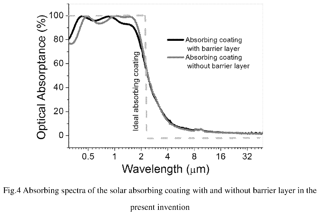
[0041]The absorbing coating according to embodiments of the invention provides an absorbing coating with an excellent optical performance and a thermal and environmental stability. The optical properties can reach a value of α>95% and ε≤4% at temperature below 200° C., and the coating withstands the thermal cycles between a room temperature and application temperature (up to 250° C.) without loss of adherence and optical properties.

Problems solved by technology

For large area applications, there are disadvantages such as complex coating process and high demands of accuracy and stability of coating equipment control.
Firstly, Oxygen or other corrosive elements from the atmosphere corrode the top layer of the coatings, and permeate towards the following absorbing layers, generally resulting in a reduction of α and an increase of ε. Secondly, elements diffusion between the bottom infrared reflective layer and absorbing layer causes again the degradation.
Thirdly, during the lifetime of a solar absorbing coating, such coating is exposed to numerous thermal cycles which may cause delamination or peel-off of coatings that result in a complete failure of a solar energy collector having coating.

Method used


Image

  • Spectrally selective solar absorbing coating and a method for making it
  • Spectrally selective solar absorbing coating and a method for making it
  • Spectrally selective solar absorbing coating and a method for making it

Examples


example 1

[0063]The specific steps of the preparation process of the above example 1 on glass substrates are as following:

[0064]1) Cleaning of the glass pane: First, A glass pane was ultrasonically cleaned in a neutral detergent solution and thereafter rinsed in deionized water. Then, the glass pane was placed in the entrance chamber of the magnetron sputtering equipment and performed second cleaning step, using an RF plasma source to bombard the glass pane surface. The process parameters were as following: RF source sputtering power was 200 w, flow rate of working gas Ar (purity 99.99%), was 45 sccm, the working pressure was 9.8×10⁻² mTorr, and sputtering time was 360 s.

[0065]2) The cleaned glass substrate was passed from the entrance chamber to the sputtering chamber of the deposition equipment. The base pressure of the sputtering chamber was lower than 6×10⁻⁶ Torr.

[0066]3) Forming the infrared reflective layer Al on the glass substrate: A metal Al target (purity 99.7%) was magnetron sputte...

example 2

[0074]Example 2: The coating processing was same as that of the example 1, except of adding the barrier layer CrNx between IR reflective Al and absorbing sublayer metal Cr. The processing parameters of the barrier layer CrNx were as follows: the sputtering power was 1500 w, the working pressure was 3 mTorr, the working gas Ar (purity 99.99%) flow rate was 50 sccm, the working gas N2 (purity 99.99%) flow rate was 50 sccm, the substrate moving speed was 2 m / min and the substrate was moved back and forth 3 times under the Cr target, and the substrate temperature was room temperature.

[0075]The multilayer stack, example 2 was then heated in air at 250° C. for 370 hr.

example 3-15

[0076]The coating processing parameters were same as the above detailed description for example land example 2, except of the coating processing of the composite absorbing layer.

[0077]1) The substrate moving speed and the number of the passes were determined according to the thickness of the film being sputtered.

[0078]2) When coating CrNx layer, the flow rate of working gas N2 was chosen randomly between 50 sccm and 100 sccm.

[0079]3) When coating CrNyOz layer, the flow rate of working gas O2 was chosen randomly between 10 sccm and 50 sccm.

[0080]For the examples in the present embodiment of the invention, the 0.3-2.5 μm reflective spectra were measured using a spectrophotometer at room temperature, which can be used to calculated the absorbing spectra in accordance to spectral absorptance α being expressed in terms of total reflectance ρ for opaque materials, α=100−ρ(%). The solar absorptance was obtained by numerical integration of the above absorbing curves over the solar distribut...


PUM

PropertyMeasurementUnit
thicknessaaaaaaaaaa
thicknessaaaaaaaaaa
thicknessaaaaaaaaaa

Abstract

A spectrally selective solar absorbing coating includes a multilayer stack including, from the substrate to the air interface: substrate (1), infrared reflective layer (2), barrier layer (3), composite absorbing layer (4) consisting of metal absorbing sublayer (4.1), metal nitride absorbing sublayer (4.2), and metal oxynitride absorbing sublayer (4.3), and antireflective layer (5). Therefore, the solar absorbing coating has good high and low temperature cycle stability and superior spectrum selectivity, with a steep transition zone between solar absorption and infrared reflection zones. It has a relatively high absorptance α>95%, and a low thermal emissivity ε≤4%, PC (performance criterion) =−0.3. The solar absorbing multilayer stack can be obtained by reactively magnetron sputtering the metal target in argon or other inert gas with some amounts of gas containing oxygen or nitrogen or their combination.

Description

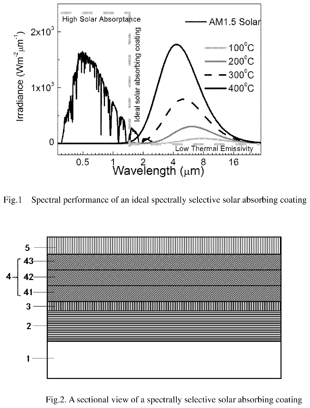
CROSS REFERENCE TO RELATED APPLICATIONS[0001]This application is a 371 U.S. National Phase of International Application No. PCT / CN2016 / 071428, filed Jan. 20, 2016, which claims the benefit of priority to Chinese application Nos. 201510158664.5, filed Apr. 3, 2015, and 201510550161.2, filed Sep. 1, 2015, which are each incorporated by reference herein in their entireties.FIELD[0002]The invention involves a spectrally selective solar absorbing coating and a method for making it.DESCRIPTION OF THE RELATED ART[0003]Spectrally selective solar absorbing coating is a key material in solar energy collector. In order to obtain the high solar-thermal conversion efficiency, the solar absorbing coating should absorb much of the incident solar energy (in the wavelength from 0.3 μm to 2.5 μm) while losing very little heat by re-radiation (at wavelength greater than 2.5 μm). Specifically, solar absorptance (α) is defined as the relationship between the solar energy absorbed by the coating relative...

Claims


Application Information

Patent Timeline
Patent Type & Authority Patents(United States)
IPC IPC(8): G06K7/10B32B15/04H01L31/0216C03C17/36B32B15/20B32B9/04F24S70/30B32B9/00B32B15/18F24S70/20C23C28/00C23C14/06C01G37/02C01B33/12
CPCC23C28/322C23C28/34C23C28/345F24S70/20C23C14/0641C23C14/0676B32B15/043C03C17/366B32B15/04B32B15/18H01L31/02168C03C17/3649F24S70/30B32B9/041B32B15/20C03C17/3626B32B9/00C01B33/12B32B2307/732C01G37/02B32B2307/40B32B2307/418B32B2307/50Y02E10/40B32B2255/06B32B2307/416F24S70/225Y02E10/50
Inventor LIU, JINGSUN, ZHIQIANGYANG, ZHONGZHOUWANG, HONG
Owner CHINA BUILDING MATERIALS ACAD
Why Eureka
Try Eureka