High performance bioabsorbable stent

a bioabsorbable, high-performance technology, applied in the direction of prosthesis, surgery, coating, etc., can solve the problems of insufficient bearing power, inability to use stents, and insufficient radial force of blood vessels, and achieve excellent deformability, good capability, and excellent safety for humans

Active Publication Date: 2021-11-02
JAPAN MEDICAL DEVICE TECH +1
View PDF49 Cites 0 Cited by
  • Summary
  • Abstract
  • Description
  • Claims
  • Application Information

AI Technical Summary

Benefits of technology

[0034]The stent of the first aspect of the present invention is excellent in deformability because the stent contains a predetermined amount of Zn, Zr, and Mn in combination with 90 mass % or more of Mg. Further, the stent of the first aspect of the present invention excels in safety to humans because unavoidable impurities selected from the group consisting of Fe, Ni, Co, and Cu is contained in 30 ppm or less, and the stent is free from rare metals and aluminum. Magnesium content is more preferably 93 mass % or more, and still more preferably 95 mass % or more.
[0035]According to the first aspect of the present invention, since the above-mentioned core structure has a high level smooth surface Ra of 0.20 μm or smaller (preferably Ra of 0.10 μm or smaller) as a pretreatment for forming the above-mentioned corrosion resistant layer so as to attain a smooth corrosion resistant surface of the stent, the obtained stent has a good capability of following physical change during diameter reduction and diameter expansion.
[0036]The stent has a magnesium fluoride layer throughout a smooth surface of the core structure formed of the magnesium alloy with the above-mentioned composition. The stent not only excels in anti-corrosiveness, but also excels in deformation followability. In addition, the hydrophilicity of the magnesium fluoride layer enhances adhesiveness between the biodegradable polymer layer formed on the magnesium fluoride layer and the magnesium fluoride layer.
[0037]The corrosion resistant layer preferably has a thickness of 1 μm or larger and 10 μm or smaller. The above-mentioned corrosion resistant layer enables to obtain a stent having desired anti-corrosiveness, deformation followability, and adhesiveness with polymer coating.
[0038]In the stent according to the first aspect of the present invention the above-mentioned core structure and the corrosion resistant layer are made of biodegradable materials, so that the stent is gradually biodegradable in the living body over about one year.
[0039]According to the first aspect of the present invention, it is possible to obtain a stent being capable of having a significant difference in temporal reduction of the radial force in the plasma imitation solution (EMEM+10% FBS) at 37° C. under 5% CO2 atmosphere, as well as in coronary arteries of pigs as compared with a stent (bare core structure) which is outside the scope of the present invention, so that the stent according to the first aspect of the present invention can maintain radial force at least one month and longer (e.g., for three to six months).

Problems solved by technology

However, although coronary-arteries stent surgery gains popularity nowadays, there have been still many cases to cause complications at a certain period of postoperative time.
However, the polymer stent described in Patent Document 1 has a problem that such a stent is weaker in strength than metal stents, resulting in insufficient bearing power, i.e., radial force of blood vessel.
Even if the bioabsorbable polymer stent would achieve a radial force equivalent to that of the metal stent by enlarging thickness (strut), such a stent is not practical because of increased restenosis rate as well as deterioration in delivery of the stent to the affected part.
The stent with a larger strut (for example, 150 μm) is reported to be inappropriate for application to the coronary arteries with a small caliber of 3 mm or less, to have low flexibility, and to be a cause of re-stenosis or stent thrombosis due to defect from excessive expansion of blood vessel wall.
On the other hand, the bare metal stent of a bioabsorbable magnesium alloy body also has a problem that mechanical strength is spoiled immediately during expansion in an aqueous solution because of acceleration of decomposition (corrosion) throughout the surface where water molecules are in contact.
Accordingly, such a bioabsorbable magnesium stent has difficulty in practical application.
Considering the requirement to maintain sufficient blood vessel bearing power (radial force) for three to six months after stent implant, the bioabsorbable magnesium has by no means suitable characteristics.
These attempts described in Patent Documents 4 and 5 should have suppressed the rise of pH caused by corrosion of magnesium alloy, but such attempts sometimes have ended up fatal damage in physical properties (particularly radial force) of the stent body.

Method used


Image

  • High performance bioabsorbable stent
  • High performance bioabsorbable stent
  • High performance bioabsorbable stent

Examples


example 1

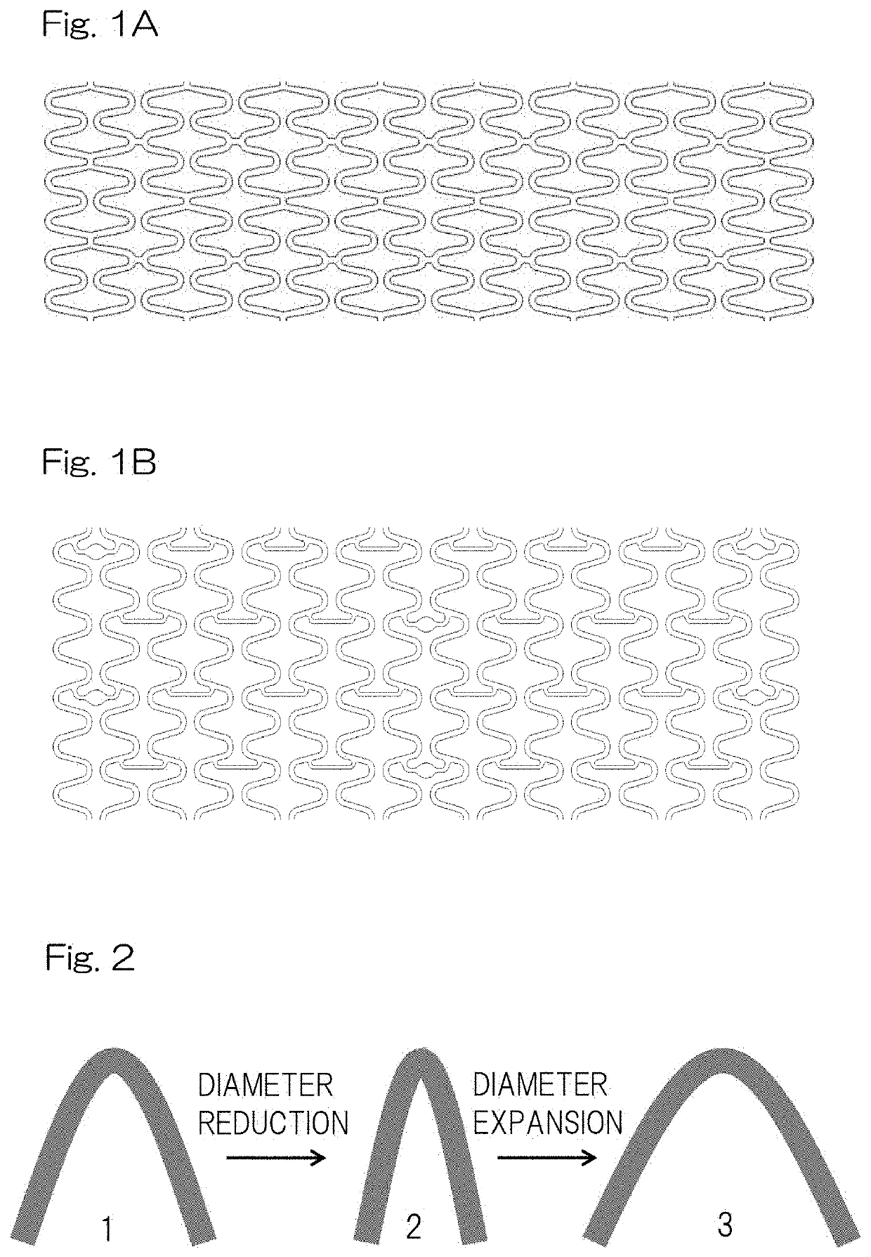
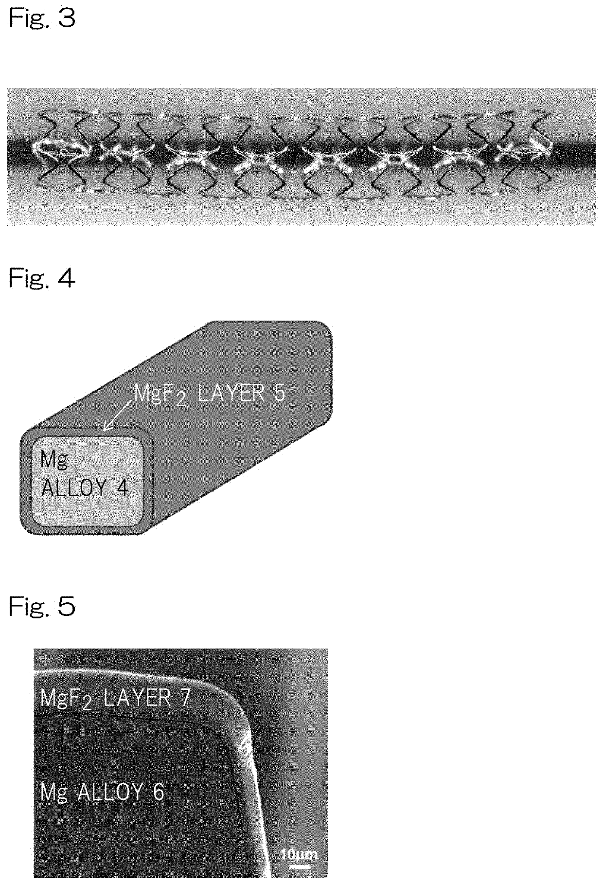
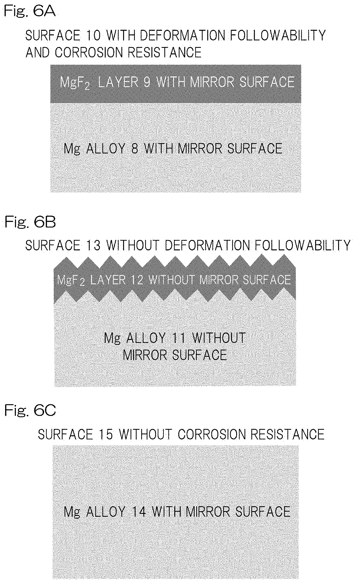
[0122]A stent scaffold having an Ra of 0.57±0.18 μm was polished by electrolytic polishing so that the edge had a smooth (round) surface with an Ra of 0.05±0.01 μm, and then immersed in a 27 M hydrofluoric-acid aqueous solution (2 mL) and reciprocally moved at a rate of 100 rpm. Then, the stent was taken out after 24 hours, and subjected to ultrasonic cleaning sufficiently with acetone aqueous solution followed by drying the core structure for 24 hours at 60° C. under vacuum. The surface of the stent had a MgF2 layer with a thickness of not more than 10 μm as shown in FIGS. 4, 5 and 6A. The significant difference in Ra was not observed between before fluoridation processing and after fluoridation processing. After crimping thus-obtained stent sample in the balloon catheter, ethylene oxide gas (EOG) sterilization was performed to the prepared sample. A total of five samples were prepared on the same conditions as this condition.

example 2

[0123]A stent scaffold having an Ra of 0.57±0.18 μm was polished by electrolytic polishing to have an Ra of 0.20±0.01 μm, and then immersed in a 27 M hydrofluoric-acid aqueous solution (2 mL) and reciprocally moved at a rate of 100 rpm. Then, the stent was taken out after 24 hours, subjected to ultrasonic cleaning sufficiently with acetone aqueous solution followed by drying the core structure for 24 hours at 60° C. under vacuum. The surface of the core structure had a MgF2 layer with a thickness of not more than 10 μm as shown in FIG. 6A. The significant difference in Ra was not observed between before fluoridation processing and after fluoridation processing. At the end, after crimping thus-obtained stent sample in the balloon catheter, EOG sterilization was performed to the prepared sample. A total of five samples were prepared on the same conditions as this condition.

example 3

[0152]The disk sample (diameter of 5 mm and thickness of 1 mm) with an Ra of 0.05±0.01 μm was immersed in a 27 M hydrofluoric-acid aqueous solution (2 mL) and shaken at 100 rpm. After 24 hours the disk was taken out and fully washed ultrasonically with acetone aqueous solution, followed by dried at 60° C. for 24 hours under vacuum. A total of three samples were prepared on the same conditions as this condition.


PUM

PropertyMeasurementUnit
Raaaaaaaaaaa
surface roughnessaaaaaaaaaa
Raaaaaaaaaaa

Abstract

To provide a stent excellent in deformability, capable of maintaining a radial force for a longer period of time, and having bioabsorbability and a method of producing the same. The bioabsorbable stent has a core structure including a magnesium alloy and a corrosion resistant layer on the core structure, wherein the core structure is formed from a magnesium alloy containing 90 mass % or more of Mg as a main component, Zn, Zr, and Mn as accessory components, and 30 ppm or less of unavoidable impurities selected from the group consisting of Fe, Ni, Co, and Cu, and the alloy excluding aluminum and at least one sort of rare earths selected from the group consisting of Sc, Y, Dy, Sm, Ce, Gd, and La; and the corrosion resistant layer containing magnesium fluoride as a main component with a hydrophilic smooth surface is formed on the core structure with a smooth surface.

Description

CROSS REFERENCE TO THE RELATED APPLICATION[0001]This application is a continuation application, under 35 U.S.C.§ 111(a), of international application No. PCT / JP2018 / 002753, filed Jan. 29, 2018, which claims priority to Japanese patent application No. 2017-014668, filed Jan. 30, 2017, the entire disclosure of which is herein incorporated by reference as a part of this application.FIELD OF THE INVENTION[0002]The present invention relates to a bioabsorbable stent that is implanted in a stenosis part or an occlusion part, especially in the coronary arteries, in lumen of living body so as to keep the inserted part open, and to be gradually degraded in the living body.BACKGROUND ART[0003]The ischemic heart diseases (myocardial infarction, angina, etc.) caused by stenosis and occlusion of the coronary arteries are critical diseases which disturb supply of the blood (nutrition, oxygen, etc.) to a cardiac muscle, and are mentioned to the second place of the cause of Japanese death. As medica...

Claims


Application Information

Patent Timeline
Patent Type & Authority Patents(United States)
IPC IPC(8): A61L31/02A61L31/14A61L31/06A61L31/10A61L31/16A61F2/90A61F2/958
CPCA61F2/90A61L31/022A61L31/148A61F2/958A61F2210/0004A61F2310/00011A61F2310/00041A61F2310/00425A61L31/06A61L31/10A61L31/16A61L2420/00A61F2/82A61L31/088A61L2420/08A61L2300/416C08L67/04
Inventor SASAKI, MAKOTOKOGA, YUKIOKAZAWA, YUKIUEDA, HIRONORIINOUE, MASASHI
Owner JAPAN MEDICAL DEVICE TECH
Why Eureka
Try Eureka