
System, method and apparatuses for reduced-emission micro oil refinery

a technology of micro-oil refinery and micro-oil refining, which is applied in the direction of hydrocarbon oil refining, hydrocarbon oil treatment, multiple-effect/fractional condensation, etc., can solve the problems of government tolerating sun-blocking smog, disrupting the process, and affecting the health of the population, so as to reduce the emission of combustion

Active Publication Date: 2022-01-04
DESIGNER FUELS LLC
View PDF2 Cites 0 Cited by
  • Summary
  • Abstract
  • Description
  • Claims
  • Application Information

AI Technical Summary

Benefits of technology

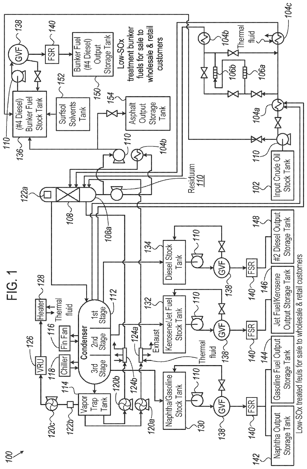
[0019]The invention overcomes the above problems by disclosing a cost-efficient system and a process of refining crude oil to extract higher-purity, cleaner-burning designer fuels, like diesel fuel, gasoline fuel, jet / kerosene fuel, bunker fuel and a chemical-rich asphalt / residuum, from any kinds of heavy or light, sweet or sour crude oil feedstock, to produce reduced combustion emissions of SOx, NOx and other unwanted pollutants into the atmosphere.
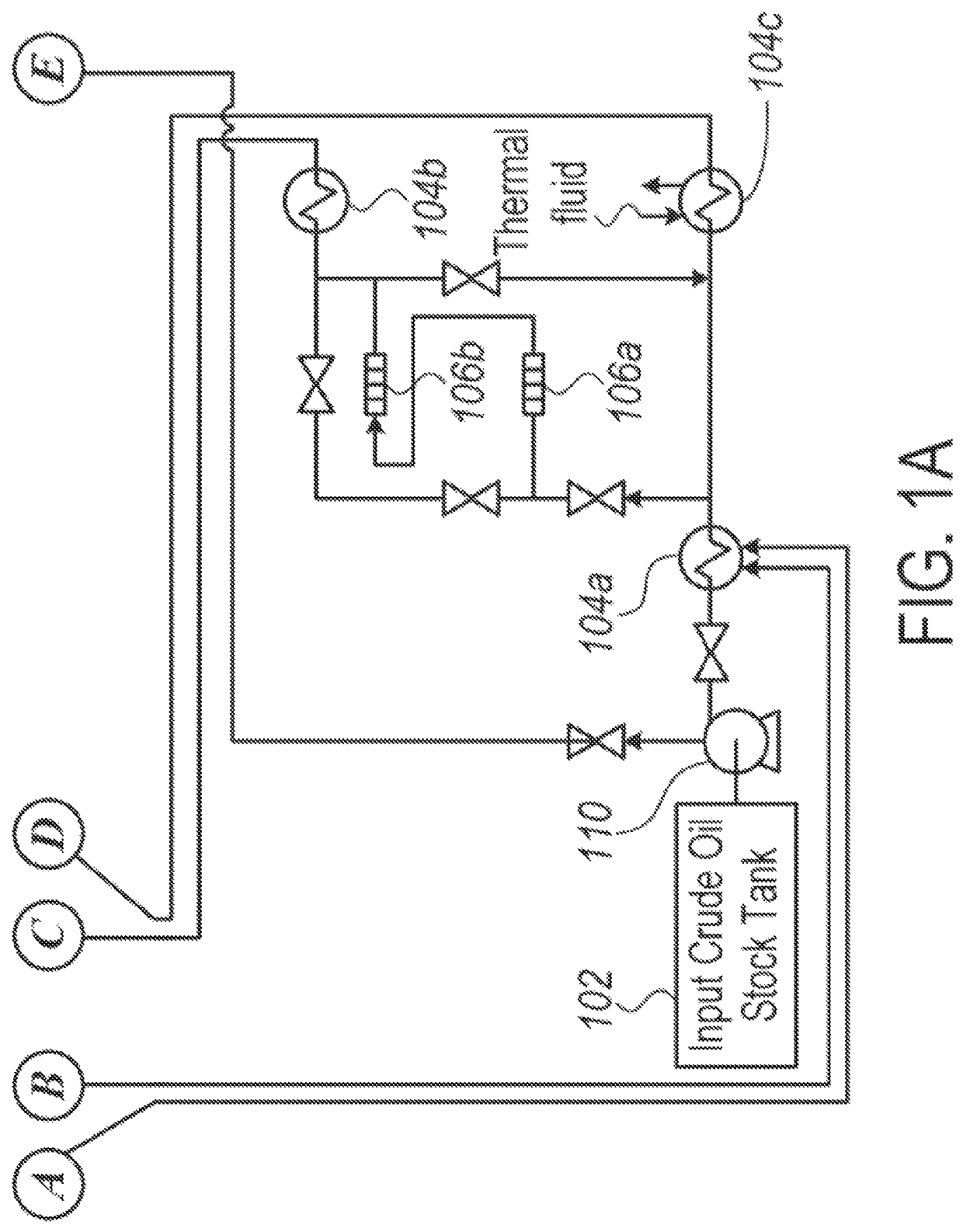
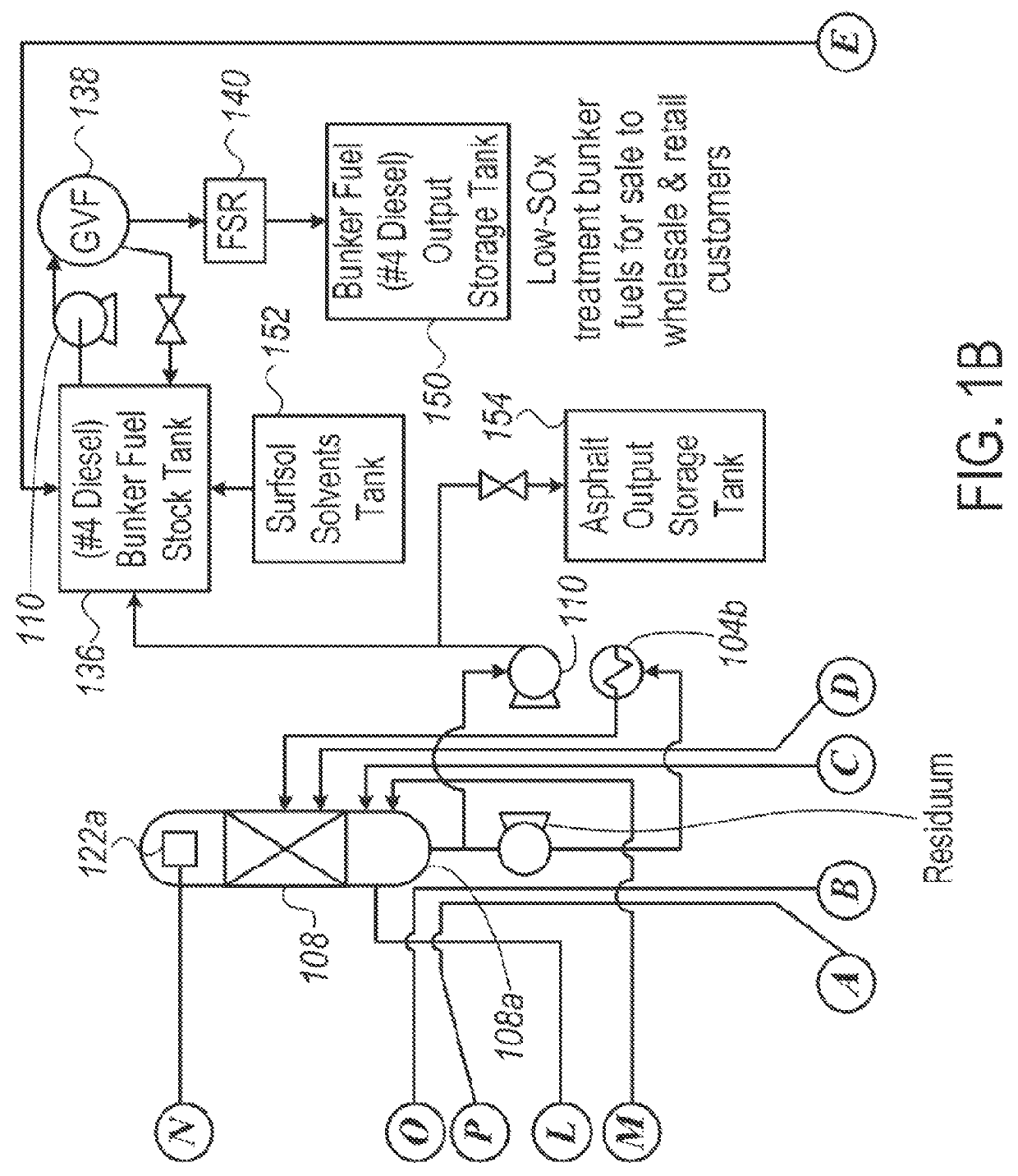
[0020]In the preferred embodiment of the present invention, a system for refining crude oil to produce high purity, cleaner-burning designer fuels in a micro-crude oil refinery with reduced refining emissions is described. The system comprises of three sections: a crude section, a vapor section and a condensate section. The crude section comprises of following devices: a crude oil stock tank, a plurality of heat exchangers, a chemical additive tank, a plurality of centrifugal pump or positive displacement pump, a plurality of valves and a reactor. The crude oil stock tank stores the crude oil feedstock. The plurality of heat exchangers heats up the crude oil to optimum temperature range according to the flow of crude oil to different devices and the movement of crude oil is controlled by plurality of valves. The chemical additive tank stores the viscosity-reductant additive which is contacted with the crude oil to breakdown heavy chain hydrocarbons into light chain hydrocarbon. The pre-treatment of the crude oil with a low-cost viscosity-reductant additive reduces the viscosity and increases API gravity of the crude oil. The centrifugal pump or positive displacement pump is configured to properly mix the crude oil with the viscosity-reductant additive. The hot crude oil enters into the reactor which is designed to carry out two novel methods of spray cracking and vacuum flashing of the crude oil to separate out heavy chain hydrocarbon, light chain hydrocarbon and by-products. This method of spray-cracking and vacuum-flashing uses less energy and is more efficient than conventional methods, and can be completely automated.

Problems solved by technology

No longer are governments tolerating the sun-blocking smog and respiratory harm to their populations caused by unregulated fossil fuel combustion emissions.
Scientific studies worldwide estimate that SOX and NOX emissions from fossil fuels are responsible for the deaths of 10s of 1000s of children and the elderly, due to respiratory harm from fossil fuel combustion pollutants.
The presence of water in the reactor may cause a significant portion of the de-metallization agent and metal oxides to precipitate from the liquid phases and thereby disrupt the process.
The process involves transferring the oxidized hydrocarbon feedstock stream into an evaporator or distillation column for carrying out the separation process and to remove the by-product including acids, acetone and acetaldehyde which makes the entire operation an expensive process.
Sulfur removal typically comprises utilization of various desulfurization processes, often requiring extreme operating conditions, and incorporation of expensive equipment, often associated with high maintenance costs.
However, it is heavy process and requires extensive secondary and tertiary recovery technology.
The problems which are mainly encountered with these processes include bacterial strain availability, economic value and refinery wastes.
Other problems linked to processes with contacting crude oil with bacterial strains include plugging of the reservoir rock by the bacterial mass in undesirable locations and acidification of the crude oil by the bio production of hydrogen sulfide in the reservoir.
The presence of water in the reactor may sometimes disrupt the operation of the reactor.
The problem is that distressed fuel oil and residues contain high-sulfur concentration, nitrogen; asphaltenes shows a tendency to form carbon or coke on the high-cost catalyst, thereby altering its function and wasting money in the process.
Further, prior art use of the sparging technique, performed in the reactor tank for cracking the crude oil, is comparatively inefficient, while the added cost of the sparging gases (like methane, helium, nitrogen, butane, carbon dioxide or any other inert gas introduced into the reactor vessel along with crude feedstock to complete the cracking process) only further increases the cost of the refining processes that use sparging.
In the crude-oil processing methods known in the above prior arts, they possess several limitations and drawbacks which need to be overcome.
The prior arts have limited scope to address the problems encountered and they are less efficient in minimizing the SOX and NOX emissions, increasing fuel lubricity and burn-efficiency in engines.
Moreover, they are incapable of achieving the so-called targeted low-sulfur and low-nitrogen emission fuels.
Moreover, most of these prior art processes use costly heaters, requiring costly fuels for high-temperature heat to break the asphaltenes and paraffins from the crude.
And these prior art processes are inefficient, because they do not completely recycle, nor use, the exhaust gases and left-over contaminants from their processes into a valuable residuum or asphalt by-product.
While such prior art processes and techniques endeavor to solve one problem, they create other problems due to their processes being too energy intensive or cost intensive or uneconomical or inefficient or more pollutive.

Method used


Image

  • System, method and apparatuses for reduced-emission micro oil refinery
  • System, method and apparatuses for reduced-emission micro oil refinery
  • System, method and apparatuses for reduced-emission micro oil refinery

Examples


working examples

[0064]Example 1: The table as shown below is an example, that illustrates the breakdown of the higher-purity, cleaner-burning designer fuels (in %) which may be produced from the process, when light crude oil having >27 API gravity is used as the input crude oil feedstock. The ratio amounts of different fuels produced in the process is completely based upon the characteristics of the input crude oil, including viscosity, gravity, sulfur content, asphaltene content, paraffin content. Based on these parameters, the automation process calculates the most optimal mix of output fuel depending on the real-time price and demands of the fuels. If the input crude oil has an API of 60% of its volume as Asphalt and 25 gravity, which is light crude oil, then that will produce a wide range of fuels as shown in table below. This table may be used for determining profits and the amounts of ester additives to be added into the finished fuels.

[0065]

TABLE 1Annual fuel production ratios from the proce...


PUM

PropertyMeasurementUnit
densitiesaaaaaaaaaa
temperatureaaaaaaaaaa
pressureaaaaaaaaaa

Abstract

A system and process for refining crude oil to produce higher-purity, cleaner-burning designer fuels with reduced emissions. The crude oil may be treated with viscosity-reductant additives, which reduces viscosity by up to 50% and increases API gravity by more than 2 points. The method of spray-cracking and vacuum-flashing of crude oil separates light end chains and heavy end chains inside the reactor. The vapor is condensed into designer fuels like bunker, diesel, jet / kerosene fuel, naphtha and gasoline fuel using multi-stage horizontal reverse condensate-condenser. The GVF centrifuges are configured to separate targeted fuels of desired density value as per their ideal fuel densities, which carry out centrifugal polishing to generate targeted fuel products of desired density and hydrocarbon molecules of desired purity values. These designer fuels are further treated with desulfurization additive.

Description

TECHNICAL FIELD[0001]The invention generally relates to a modular or micro / mini crude oil refinery that processes 10,000-100,000 barrels of crude oil per day, and more particularly, relates to an environmentally-friendlier and safer, low-temperature and low-pressure system, process and apparatus for refining crude oil with reduced refining emissions to produce higher-purity, cleaner-burning bunker fuels, jet fuels, diesel fuels and gasoline fuels with reduced combustion emissions of SOx and NOx, using a software-controlled automation method to control the production of these designer fuels.BACKGROUND[0002]The properties of hydrocarbons depend on the number and arrangement of the carbon and hydrogen atoms in the molecules. Hydrocarbons containing up to four carbon atoms are usually gases, those with 5 to 19 carbon atoms are usually liquids, and those with 20 or more carbon atoms are solids. Crude oils range in consistency from water to tar-like solids, and in color from clear to blac...

Claims


Application Information

Patent Timeline
Patent Type & Authority Patents(United States)
IPC IPC(8): C10G31/10C10G31/06C10G53/02C10G55/02
CPCC10G31/10C10G31/06C10G53/02C10G55/02C10G2300/202C10G2300/206C10G2300/308C10G2300/405C10G2300/4006C10G2300/4012C10G2300/4081C10G2300/80C10G55/04C10G29/00B01D5/0036B01D3/06B01D1/16
Inventor SNIDER, GEORGE EDYER, RICHARD JSHULTZ, LARRY M
Owner DESIGNER FUELS LLC
Learn More