Pressure vessel

a pressure vessel and pressure technology, applied in the field of pressure vessels, can solve the problems of capsule bursting and capsule crushing, and no suitable autoclave design is currently availabl

Inactive Publication Date: 2003-07-31
SORAA
View PDF15 Cites 124 Cited by
  • Summary
  • Abstract
  • Description
  • Claims
  • Application Information

AI Technical Summary

Benefits of technology

0035] In one embodiment, a top seal 120 and bottom seal 122 are interposed between the top and bottom punches 100, 102, respectively, and the pressure transmission medium 14 to prevent escape of the pressure transmission medium 14. Top and bottom seals 120, 122 typically comprise steel end caps, which are optionally fitted with a ring fabricated from brass or another similarly deformable material. At least one of top and bottom seals 120, 122 is separated from contact with die 104 by a bushing 128 to prevent creation of an electrical short between the die 104 and either the at least one heating element 18 or the electrical leads connecting the at least one heating element 18 to the wattage source. The insulating bushing preferably has an internal friction between about 0.2 and about 0.7 under operating conditions, or, more preferably, between about 0.25 and about 0.5. The insulating bushing comprises at least one of pyrophyllite, talc, olivine, magnesium oxide, calcium carbonate, calcium oxide, strontium oxide, barium oxide, textilite and similar glued paper composites, merylinite clay, bentonite clay, sodium silicate, and hexagonal boron nitride.
0036] Top gasket 124 and bottom gasket 126 are typically disposed between top punch 100 and die 104 and bottom punch 102 and die 104, respectively. Alternatively, top gasket 124 and bottom gasket 126 may also be disposed between top punch 100 and top seal 120 and bottom punch 102 and bottom seal 122, respectively. At least one of top gasket 124 and bottom gasket 126 is an electrical insulator, so that die 104 does not act as an electrical short for the at least one heating element 18. In one embodiment, the insulating gasket comprises at least one of natural or synthetic rubber, Myl...

Problems solved by technology

No suitable autoclave design is currently available, however, for processing in a medium other than an inert gas and at pressures exceeding more than a few kilobar.
If the externally applied pressure is insufficient, the capsule will burst.
Conversely, if the external pressure...

Method used


Image

  • Pressure vessel
  • Pressure vessel
  • Pressure vessel

Examples


Embodiment Construction

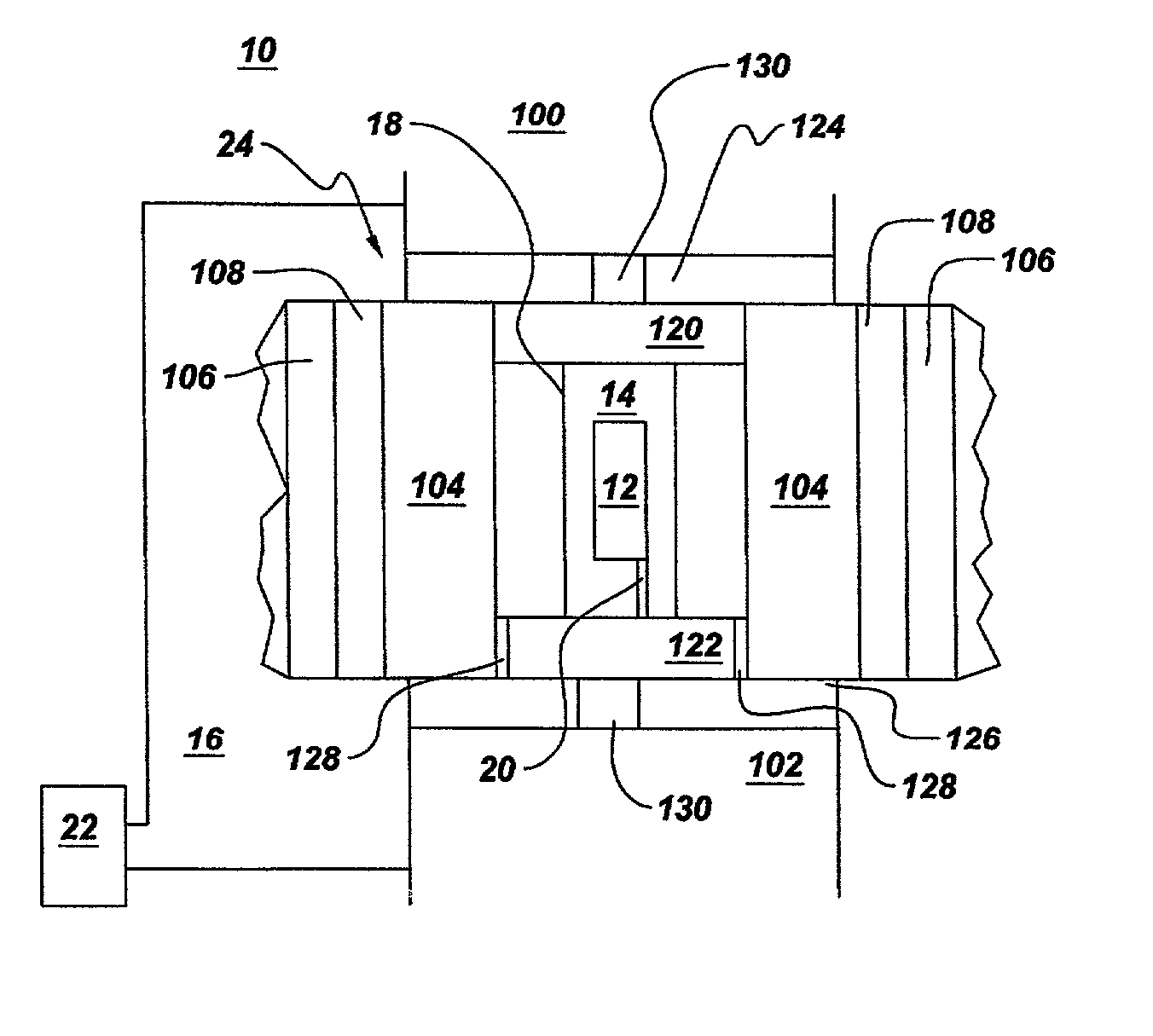
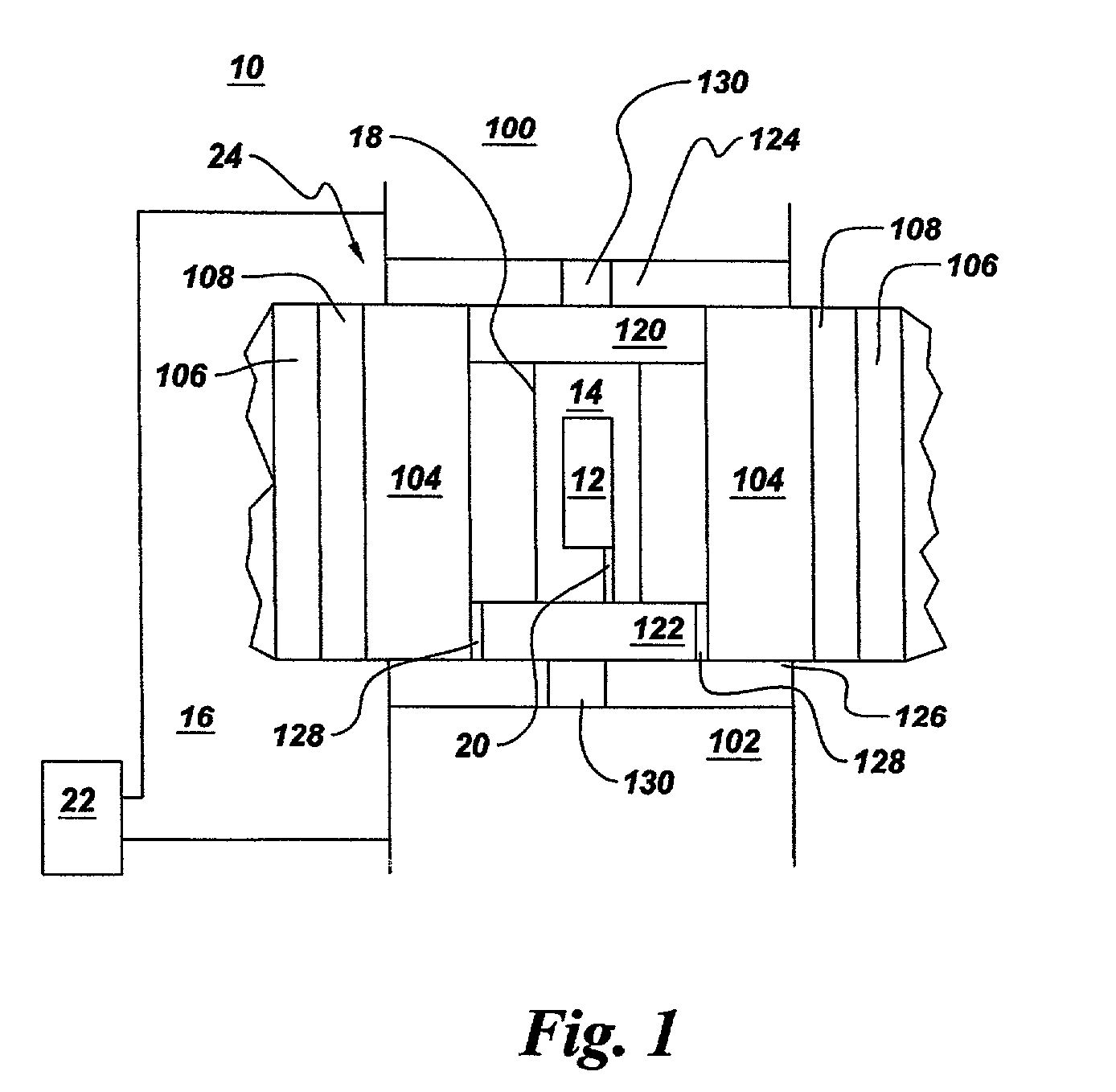
[0041] Pressure vessel tooling for use in a 1000-ton hydraulic press was fabricated as follows. A cemented tungsten carbide die having an inner diameter of about 2.0 inches, an outer diameter of 6.9 inches, and a height of 3.7 inches was shrink-fitted into a steel die sleeve. The die sleeve contained eight axial cooling channels to provide for water cooling of the die. The die and die sleeve were pressed into a belt comprising three compression-fit steel rings having outer diameters of about 10.7 inches, 14.7 inches, and 19 inches, respectively. The die, die sleeve, and steel compression rings had interferences so as to provide compression of the die. The belt assembly was then press-fitted into a fourth steel "guard" ring with an outer lip to permit lifting and transport. Brass rings with channels machined into the inner faces were attached to the top and bottom of the die sleeve, with the channels aligned with the axial cooling channels in the die sleeve so that water could be for...


PUM


Abstract

A pressure vessel for processing at least one material in a supercritical fluid. The pressure vessel includes a self-pressurizing capsule for containing at least one material and the supercritical fluid in a substantially air-free environment, a pressure transmission medium surrounding the capsule for maintaining an outer pressure on the capsule, at least one heating element insertable in the pressure transmission medium such that the heating element surrounds the capsule, a temperature measurement means for measuring a temperature of the capsule, a temperature controller for controlling the temperature and providing power to the heating element, a restraint to contain and hold in place the capsule, the pressure transmission medium, and the heating element, and at least one seal between the restraint and the pressure transmission medium for preventing escape of the pressure transmission medium. Methods of using the pressure vessel, processing a material at high temperature and high pressure in the presence of a supercritical fluid within the capsule are also described.

Description

BACKGROUND OF INVENTION[0001] The invention relates generally to pressure vessels. More particularly, the present invention relates to an improved pressure vessel for processing at least one material in a supercritical fluid.[0002] Many chemical or material synthesis processes can best be run at elevated pressures and temperatures within a vessel or cell containing either a solid, liquid, or gaseous medium. Well-known cell designs, such as those employed in commercial synthetic diamond manufacturing, can be used when the medium is a solid at room temperature. When the medium is a liquid or a gas at room temperature, reactions can be carried out at pressures of up to a few kilobar (kbar) in autoclaves. No suitable autoclave design is currently available, however, for processing in a medium other than an inert gas and at pressures exceeding more than a few kilobar.[0003] In instances where even higher pressures are needed, reactants and solvent are sealed within a capsule and then sub...

Claims


Application Information

Patent Timeline
IPC IPC(8): B01J3/00B01J3/04B01J3/06B01J19/00B01J19/02C30B1/04C30B1/12F16J15/10C30B29/38F16J13/02
CPCB01J3/062B01J19/0013B01J19/006B01J19/0073B01J19/02B01J2203/067C30B7/00B01J2219/00094B01J2219/00135B01J2219/0236B01J2219/0277B01J2219/1943B01J2219/00063B01J3/04B01J3/00B01J3/06
Inventor D'EVELYN, MARK PHILIPNARANG, KRISTI JEANGIDDINGS, ROBERT ARTHURLEONELLI, ROBERT VINCENT JR.DOLE, STEPHEN LEE
Owner SORAA
Why Eureka
Try Eureka