High temperature high pressure capsule for processing materials in supercritical fluids

a supercritical fluid and capsule technology, applied in the field of capsules, can solve the problems of capsule burst, material inside the capsule cannot be processed, contaminating the reaction mixture, etc., and achieve the effect of convenient control

Inactive Publication Date: 2003-07-31
SLT TECH
View PDF19 Cites 76 Cited by
  • Summary
  • Abstract
  • Description
  • Claims
  • Application Information

AI Technical Summary

Benefits of technology

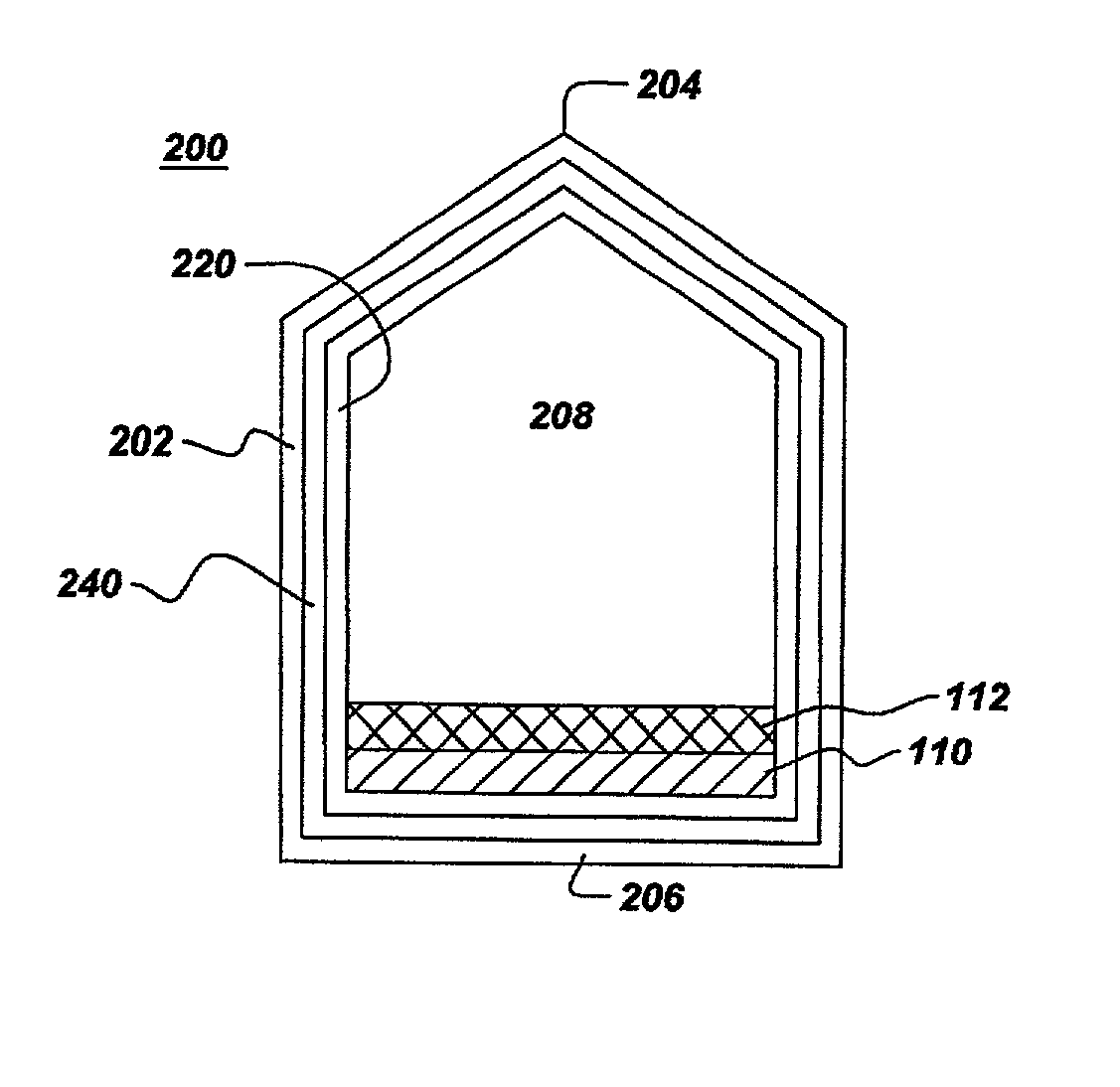
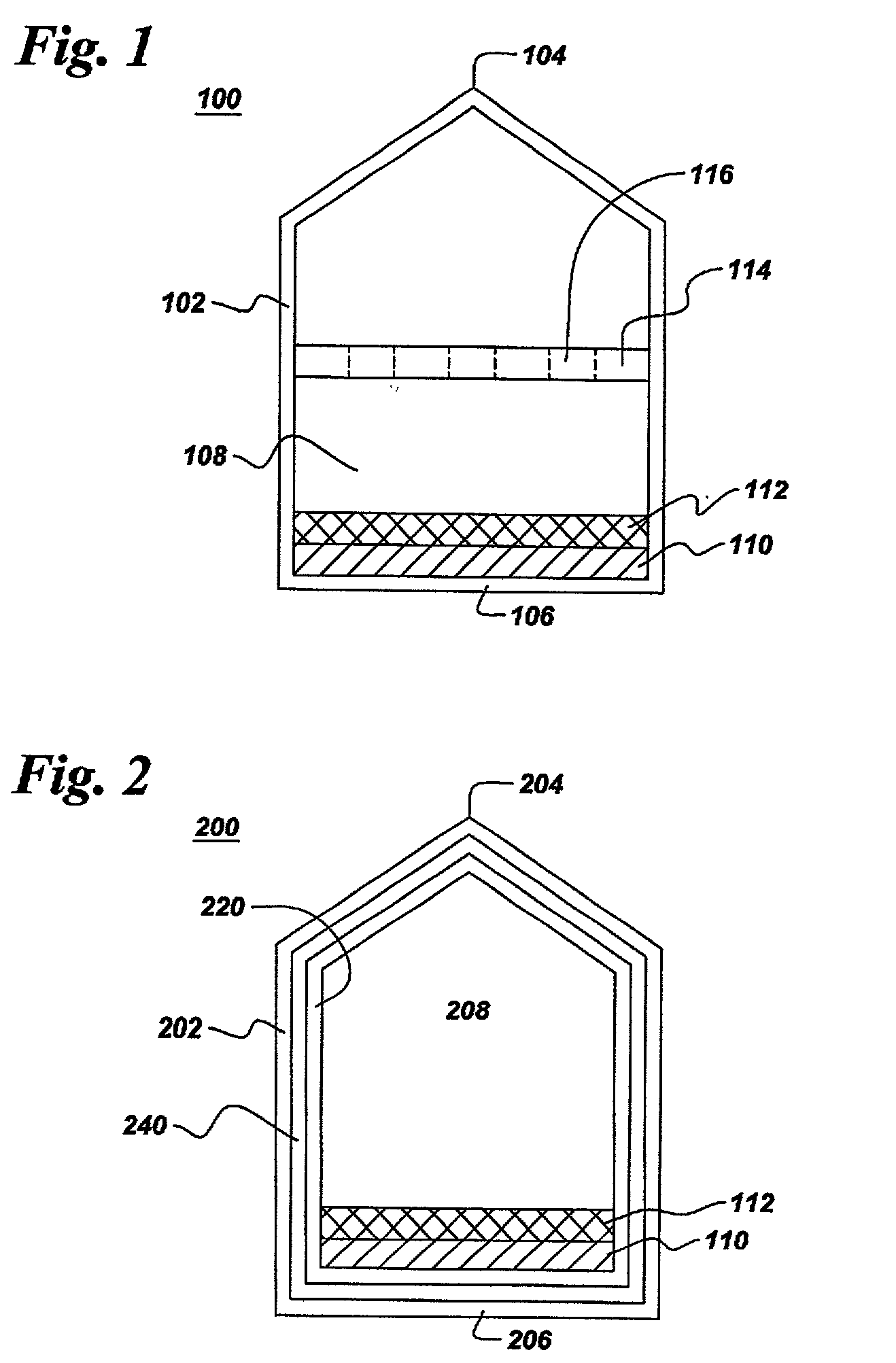
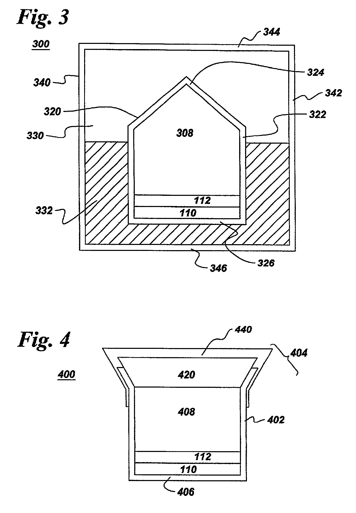
0046] Because the pressure that is needed for processing with supercritical fluids is generated internally within the capsule itself, the capsule of the present invention does not require a conventional pressure device to externally supply high pressure. In such conventional pressure devices, the pressure response, which is defined as the percent increase in cell pressure divided by the percent increase in press force that produces the increased cell pressure relative to a reference operating condition, is typically high, ranging from near unity for piston cylinder presses to about 50% for belt-type presses and multi-anvil presses. Under such circumstances, precise control of the pressure applied to the capsule via the press force is required in order to prevent the capsule from either bursting or being crushed.
0047] ...

Problems solved by technology

When such a solid or liquid is used as the SCF source, however, decomposition products other than the supercritical fluid that remain in the reaction mixture may contaminate the reaction mixture.
Additional contamination may also result from air introduced during filling of the capsule.
Once the capsule is sealed, however, the material inside the tube cannot be processed at internal pressures greater than abou...

Method used


Image

  • High temperature high pressure capsule for processing materials in supercritical fluids
  • High temperature high pressure capsule for processing materials in supercritical fluids
  • High temperature high pressure capsule for processing materials in supercritical fluids

Examples


example 2

[0052] Approximately 3.25 g of pure water was added to a 0.5 inch diameter copper tube having a closed end and an open end. The tube was then pinched off to form a capsule as described in Example 1. The capsule was embedded in salt and the capsule / salt assembly was then inserted into a cell and placed in a zero-stroke HPHT vessel as described in U.S. patent application Ser. No. ______, filed on ______ 2001, by Mark Philip D'Evelyn et al., entitled "Improved Pressure Vessel". The capsule was heated to 360.degree. C. Based on the phase diagram of water, the pressure within the capsule was approximately 1.6 kbar. The capsule / salt assembly was cooled and removed from the press, and the capsule was recovered by dissolving the salt pressure transmission medium in water. The capsule was found to contain only 1.38 g of water, indicating that 58% of the water leaked from the capsule during processing under HPHT conditions.

example 3

[0053] Approximately 0.21 g of GaN and 0.10 g of NH4F were added to a 0.5 inch diameter OFHC copper tube having a closed end and an open end. A plug having a beveled end for sealing the open end of the copper tube was machined from OFHC copper. To improve the chemical inertness of the capsule, both the plug and the interior of the copper tube were electroplated with a rhodium diffusion barrier and a gold coating, having thicknesses of 2 and 25 microns, respectively. Loading of the copper tube with GaN and NH4F was carried out under a nitrogen atmosphere within a glove box.

[0054] A capsule filler / sealing assembly similar to that shown in FIG. 7 was also located within the glove box. The guide sleeve was fabricated by reaming a 11-inch" Ultra Torr.RTM. Union through and welding a fill tube to the side. The support sleeve, having a 0.5 inch inner diameter, and top piston were fabricated from hardened tool steel, and the base flange was fabricated from stainless steel. Silicone o-rings ...

example 4

[0056] Approximately 0.58 g of GaN, 0.100 g NH4F, and 0.01 g Mg3N2 were added to a 0.5 inch diameter OFHC copper tube having a closed end and an open end. A plug having a beveled end for sealing the open end of the copper tube was machined from OFHC copper. To improve the chemical inertness of the capsule, both the plug and the interior of the copper tube were electroplated with a nickel diffusion barrier and a gold coating, having thicknesses of 2 and 25 microns, respectively. Loading of the copper tube with GaN and NH4F was carried out under a nitrogen atmosphere within a glove box.

[0057] The capsule and plug were placed inside the filler / sealing assembly described in Example 3. A 0.5 inch diameter solid rod was placed in the support sleeve below the the capsule in the fill / seal assembly so that the top 0.4 inch of the capsule protruded from the top of the support sleeve. A steel ring, having an outer diameter of 0.675 inch, was placed over the open end of the capsule. The capsule...


PUM

PropertyMeasurementUnit
Fractionaaaaaaaaaa
Fractionaaaaaaaaaa
Thicknessaaaaaaaaaa

Abstract

A capsule for containing at least one reactant and a supercritical fluid in a substantially air-free environment under high pressure, high temperature processing conditions. The capsule includes a closed end, at least one wall adjoining the closed end and extending from the closed end; and a sealed end adjoining the at least one wall opposite the closed end. The at least one wall, closed end, and sealed end define a chamber therein for containing the reactant and a solvent that becomes a supercritical fluid at high temperatures and high pressures. The capsule is formed from a deformable material and is fluid impermeable and chemically inert with respect to the reactant and the supercritical fluid under processing conditions, which are generally above 5 kbar and 550° C. and, preferably, at pressures between 5 kbar and 80 kbar and temperatures between 550° C. and about 1500° C. The invention also includes methods of filling the capsule with the solvent and sealing the capsule, as well as an apparatus for sealing the capsule.

Description

BACKGROUND OF INVENTION[0002] The invention relates generally to a capsule to be used with pressure vessels. More particularly, the invention relates to a capsule used in conjunction with a high-pressure vessel for processing at least one material in a supercritical fluid.[0003] Supercritical fluids (also referred to hereinafter as "SCF") may be used to process a wide variety of materials. Examples of SCF applications include extractions in supercritical carbon dioxide, the growth of quartz crystals in supercritical water, and the synthesis of a variety of nitrides in supercritical ammonia.[0004] Processes that employ supercritical fluids are generally performed at high pressure and high temperature (also referred hereinafter as "HPHT") within a pressure vessel. Most conventional pressure vessels not only provide a source of mechanical support for the pressure applied to reactant materials and SCF, but also serve as a container for the supercritical fluid and material being processe...

Claims


Application Information

Patent Timeline
IPC IPC(8): A61K9/64B01D9/00B01J3/00B01J3/06B01J19/02B65D1/40B65D3/22B65D6/14C30B9/00C30B29/40
CPCB01J3/008Y10T117/10B01J19/02B01J2203/0665B01J2219/00777B01J2219/0236B01J2219/024C30B7/10C30B9/00C30B29/40C30B29/406Y10T117/1024Y10T117/1092Y10T117/1004Y10T117/108B01J3/062Y02P20/54
Inventor D'EVELYN, MARK PHILIPNARANG, KRISTI JEANGIDDINGS, ROBERT ARTHURTYSOE, STEVEN ALFREDLUCEK, JOHN WILLIAMVAGARALI, SURESH SHANKARAPPALEONELLI, ROBERT VINCENT JR.DYSART, JOEL RICE
Owner SLT TECH
Why Eureka
Try Eureka