Electrosynthesis of nanofibers and nano-composite films

Inactive Publication Date: 2003-11-27
BATTELLE MEMORIAL INST
View PDF6 Cites 86 Cited by
  • Summary
  • Abstract
  • Description
  • Claims
  • Application Information

AI Technical Summary

Benefits of technology

0026] FIG. 4 is a graphical depiction of cyclic voltammograms of different polyaniline film morphologies. Curve (a) represents oriented polyaniline nanofibers on a Pt substrate synthesized according to methods disclosed herein, (b) represents oriented polyaniline nanofibers on silica spheres synthesized according to methods disclosed herein, and (c) represents a conventional polyaniline film deposited without the step-wise current process. The

Problems solved by technology

Many methods have been reported for preparing oriented nanostructures, but most of these methods cannot be applied to organic polymer materials.
Electrodes formed from films of hexacyanometallates have been made, but their instability and electrical properties remains a critical issue.
At such large overpotentials, substances present in biological samples such as ascorbic acid, uric acid and acetaminophen interfere under oxidation conditi

Method used


Image

  • Electrosynthesis of nanofibers and nano-composite films
  • Electrosynthesis of nanofibers and nano-composite films
  • Electrosynthesis of nanofibers and nano-composite films

Examples


example 1

[0078] Synthesis of Nanofibers

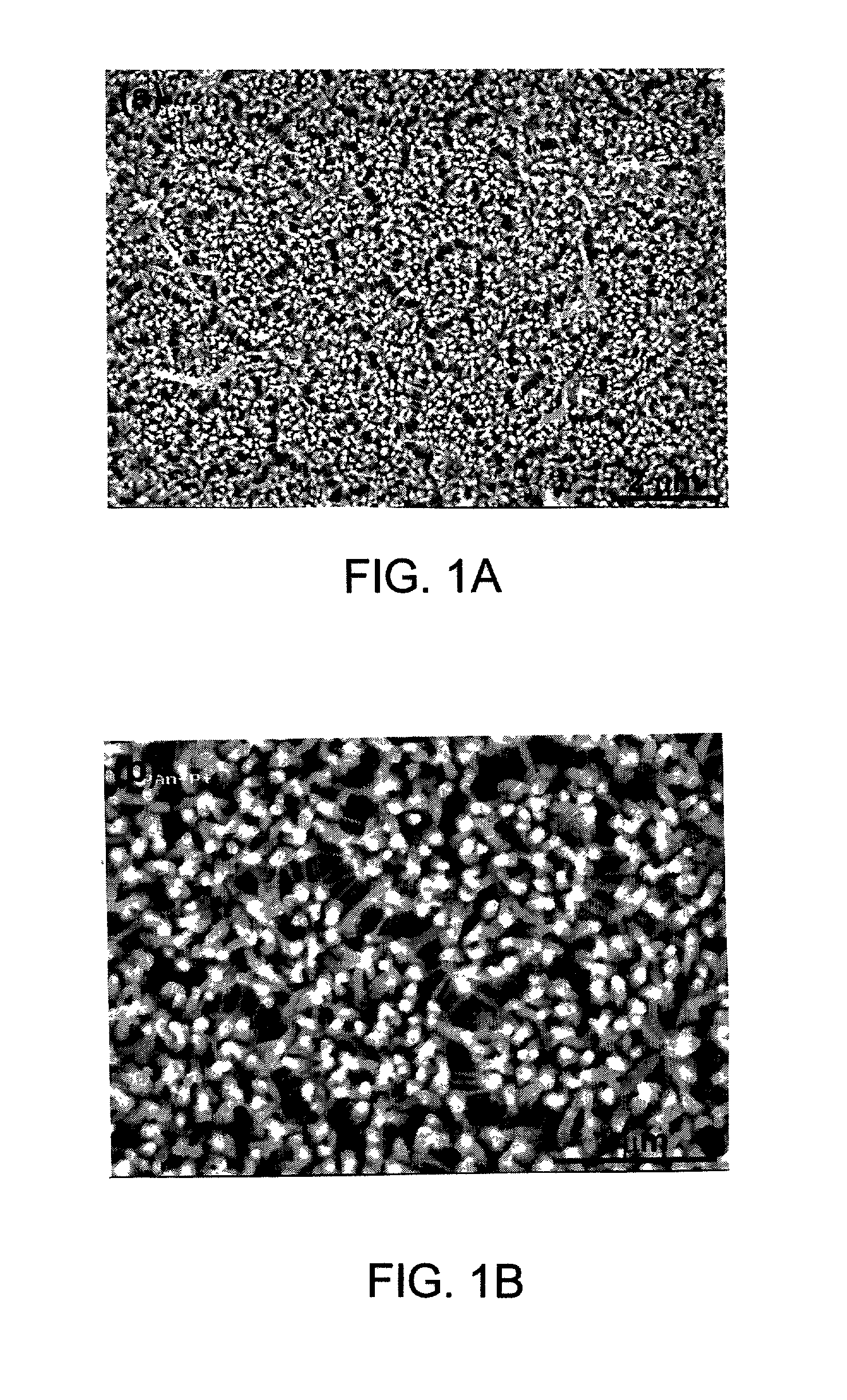
[0079] A Pt plate about 1 inch by 1 inch in size was washed thoroughly with ethanol and dried in air. The Pt plate was further rinsed in a 1 wt. % sodium dodecyl sulfate (SDS) solution and dried in air to improve the wetting behavior with water. Electrochemical deposition of polyaniline (PANI) was performed by immersing the Pt plate into an aqueous solution containing 0.5 M aniline monomer and 1.0 M perchloric acid (HClO.sub.4). The effective area of the immersed Pt plate was 4.5 cm.sup.2. Polyaniline was grown from the surface of the Pt plate by redox polymerization of aniline. The electrochemical experiments were performed on an EG & G Princeton Applied Research model 273 potentiostat / galvanostat controlled by a personal computer via EG & G Princeton Applied Research Model 270 electrochemical software. The experiments for PANI film depositions were made in an H-shape two-compartment cell, with another platinum plate used as the counter electrode. A sa...

example 2

[0087] Synthesis of Composite Films

[0088] A polyaniline nanoporous film was synthesized according to Example 1, except that the second and third constant current density steps were maintained for four hours rather than three. In addition, the working electrode was a glassy carbon disk with a surface area of 0.14 cm.sup.2 (commercially available from Bioanalytical Systems) rather than a Pt substrate.

[0089] FeHCF was electrodeposited on the polyaniline-modified electrode by immersing the electrode in a 0.1 M KCl aqueous solution containing a 0.01 M equimolar mixture of FeCl.sub.3 and K.sub.3Fe(CN).sub.6. The electrode potential was cycled between -0.20 and +0.80 V at 50 mV / s in the mixed solution of 0.1 M KCl, 0.01 M FeCl.sub.3 and 0.01 M K.sub.3Fe(CN).sub.6.

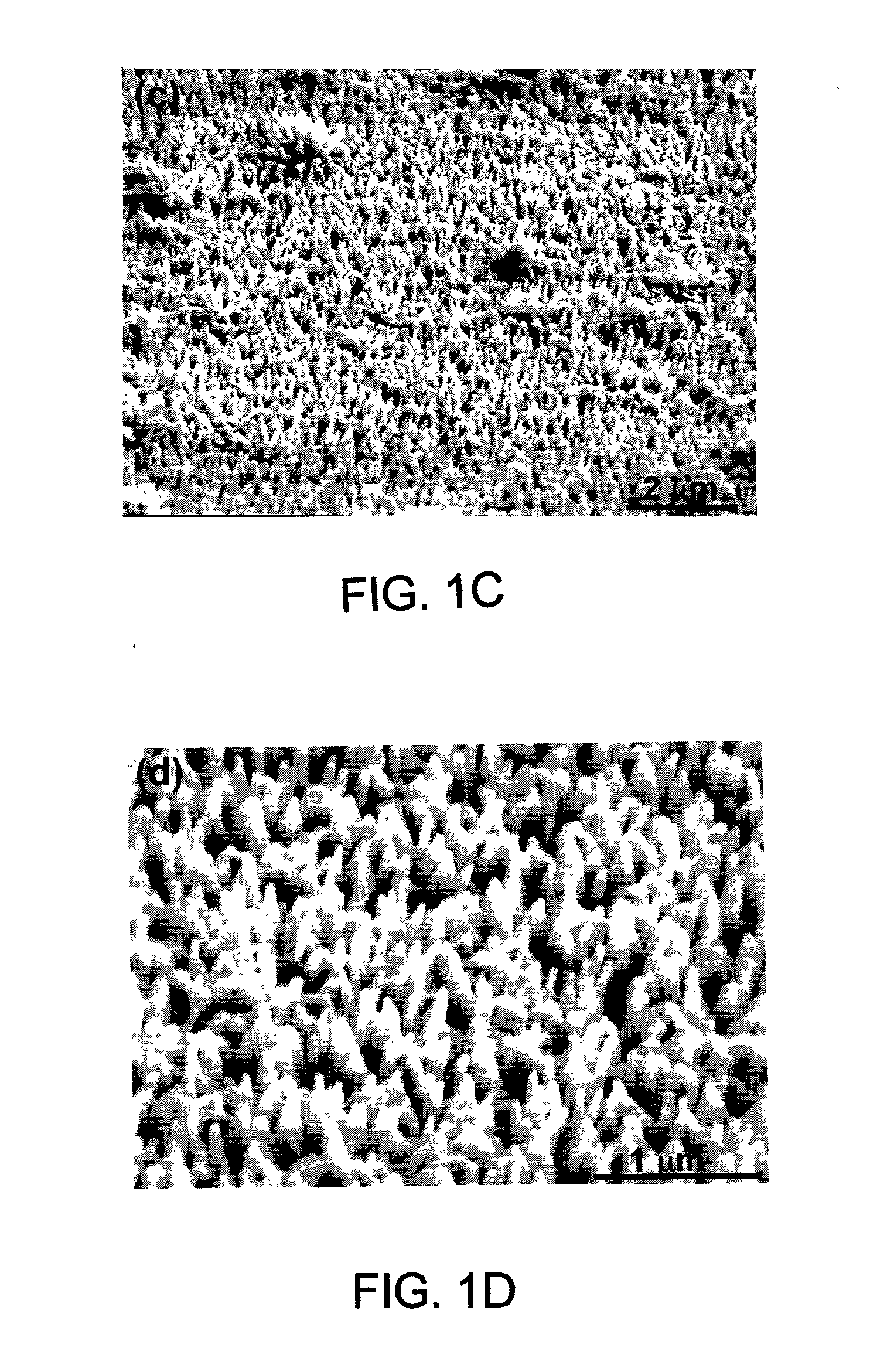
[0090] The surfaces of the polyaniline / FeHCF-modified electrode were investigated with SEM. The SEM micrographs indicated that FeHCF was deposited into the nanoporous polyaniline matrix and at least partially filled the nanopores....

example 3

[0092] Sensor

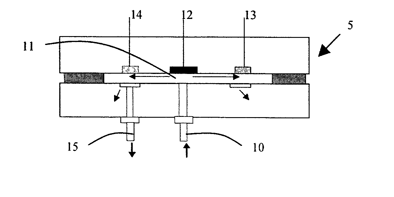
[0093] A polyaniline / FeHCF-modified glassy carbon electrode made as described above in Example 2 was used to detect the presence of hydrogen peroxide by sensing catalytic reduction of hydrogen peroxide. The amperometric detection was conducted using the flow injection analysis system shown in FIG. 7. The particular system included a peristaltic pump, a Rheodane 7125 injector with a 50-.mu.L sample loop, an interconnecting polytetrafluorethylene tubing, and a thin-layer electrochemical flow cell. Flow injection / amperometric measurements were conducted with a CH Instruments model CHI 824 electrochemical detector. The working electrode is the glassy carbon electrode embedded in a PEEK plate. A constant potential of 0.1 V was applied to the electrode. The flow rate of the carrier solution (0.1 M KCl, 0.05 M acetate buffer (pH 6.0) was 0.5 mL / min. A 50-uL sample containing hydrogen peroxide was injected from the injection valve into the carrier solution. Hydrogen peroxide wa...


PUM

PropertyMeasurementUnit
Lengthaaaaaaaaaa
Fractionaaaaaaaaaa
Diameteraaaaaaaaaa

Abstract

A method for producing an array of oriented nanofibers that involves forming a solution that includes at least one electroactive species. An electrode substrate is brought into contact with the solution. A current density is applied to the electrode substrate that includes at least a first step of applying a first substantially constant current density for a first time period and a second step of applying a second substantially constant current density for a second time period. The first and second time periods are of sufficient duration to electrically deposit on the electrode substrate an array of oriented nanofibers produced from the electroactive species. Also disclosed are films that include arrays or networks of oriented nanofibers and a method for amperometrically detecting or measuring at least one analyte in a sample.

Description

FIELD[0002] The present disclosure relates to the synthesis of nanofibers and films made from the nanofibers.BACKGROUND OF THE DISCLOSURE[0003] Many methods have been reported for preparing oriented nanostructures, but most of these methods cannot be applied to organic polymer materials. Oriented carbon nanotubes are prepared through chemical vapor deposition (CVD). Large arrays of oriented carbon nanotubes were grown from catalyst particles immobilized on porous silica or glass substrates (Li et al., Science, 274, 1996; and Ren et al., Science, 282, 1150, 1998). A gas phase reaction or similar high temperature reactions have been used to prepare oriented nanorods of ZnO (Huanh et al., Science, 292, 1897, 2001), Si (Yu et al., Physica. E., 9, 305, 2001), and silicon carbide / nitride (Chen et al., J. Phys. Chem. of Solids, 62, 1567, 2001). A solution based synthesis method has been developed to prepare oriented nanorods of ZnO.sub.2 using a hydrothermal process (Vayssieres et al., Phy...

Claims


Application Information

Patent Timeline
IPC IPC(8): C09D5/44C25D9/00
CPCB82Y30/00C25D9/00C09D5/4476
Inventor LIN, YUEHELIANG, LIANGLIU, JUN
Owner BATTELLE MEMORIAL INST
Why Eureka
Try Eureka