
Production of aligned microfibers and nanofibers and derived functional monoliths

Inactive Publication Date: 2004-11-04
UT BATTELLE LLC
View PDF4 Cites 15 Cited by
  • Summary
  • Abstract
  • Description
  • Claims
  • Application Information

AI Technical Summary

Benefits of technology

[0008] It is yet another object of the present invention to provide an inorganic fibrous structure ranging in diameter from micrometer-sized to nanometer-sized having increased surface area and enhanced anisotropic properties including conductivity, permittivity, optical attenuation and mechanical toughening.
[0063] The process of the present invention for producing and growing microfibers, nanofibers and monolith fabrication is not limited to silica materials and can be good for a variety of materials (dielectric or conductive) with various compositions that can be achieved by sol-gel reactions or other solid-precipitative reactions. The greatest feature of the present invention's field-coupled reactive process is that inorganic molecular species and clusters can be manipulated by electric field to achieve the desirable placement (localization) and quantitative accumulation of inorganic materials. One application of this feature leads to new micro- and nano-fabrication technologies such as using patterned microelectrodes or focused electron beam to create high-resolution electrostatic image patterns, which further directs the in situ nucleation and growth of desirable inorganic solid phase. This offers a refined alternative to the bottom-up fabrication based on colloids and smaller particles. Edge roughness of assembled patterns or structures can be much less when the molecular clusters are used as building-block units. Other applications of the monolithic material made by the process of the present invention include not only its use as an electrophoretic media, but also use as a catalyst, an ion exchange resin and in electronics.

Problems solved by technology

ies. Current monolith development in the field has been limited to organic polymeric media (e.g., styrene divinylbenzene-based materials) (Svec et. al.,
For GE, uniform preparation and loading of gels are labor intensive.
Only limited number of samples can be loaded per gel.
The gel typically used in laboratory applications is polyacrylamide; however, its monomer is very toxic and the gel is fragile.
To increase the maximum number of samples, the latest development in CE utilizes bundled glass capillaries, but they are still fragile and tedious to operate.
Both gels and glass capillary are not suitable for large-scale separations.

Method used


Image

  • Production of aligned microfibers and nanofibers and derived functional monoliths
  • Production of aligned microfibers and nanofibers and derived functional monoliths
  • Production of aligned microfibers and nanofibers and derived functional monoliths

Examples


example 2

[0051] A solution containing 0.2 M TEOS, 4.86 M H.sub.2O and 2.0 M NH.sub.3 in tAA (Condition 5 in Table 2) was used in the thin (1-mm path) quartz cuvette at room temperature, pulsed DC field (4.5 kHz). When the applied voltage is too high (.about.10 kV), Joule heating due to the higher conductivity of reactive solution (TEOS-H.sub.2O--NH.sub.3-tAA) relative to the pure tAA solvent used in the earlier particle alignment experiments caused solvent evaporation, which generated bubbles that stirred up the bulk solution in the cuvette reactor. Fluid flow in the solution caused the failure of electric field alignment during the in-situ precipitative solid particle formation. However, at lower voltage (1.84 kV), the bubbling from solution was reduced significantly. During the reaction, there were only a few small bubbles evolving from the high-voltage electrode surface, and this did not disturb the static structure of the precipitated gels. Thick precipitate gel solid that spans between ...

example 3

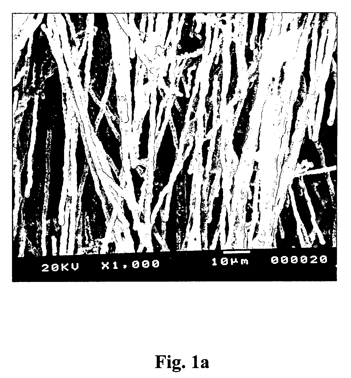
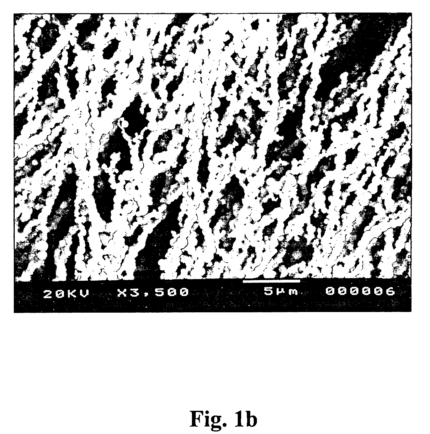
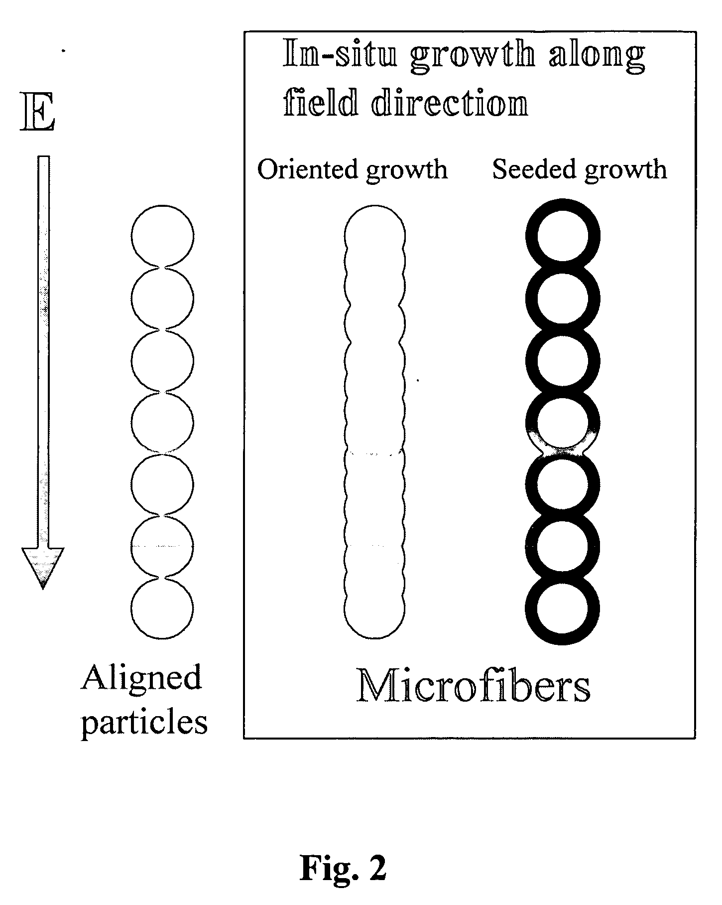
[0056] Two equal volumes of the solutions (TEOS-tAA and water-ammonia-tAA) were mixed vigorously by hand and poured into the electrofibrilation cell. The electrofibrilation cell is a standard quartz cuvette of either 1-mm path (1 mm.times.10 mm.times.45 mm) or 1-cm path (10 mm.times.10 mm.times.45 mm) with two parallel-steel-plate (.about.1 mm thickness) electrodes attached to the side walls. To enhance the rate of solid microfiber production, some pre-made silica microsphere particles were used as seeds in reaction solution (Condition 6, Table 2). The effect of seeding on nucleation, growth, aligned particle-particle connection during reaction under field, and eventually on the microstructure of the fibrils was studied. Such seed-solution mixtures were subjected to no field (as control) or 1.5 kV pulsed DC field (4.5 kHz). SEM examination of solid samples collected after 1.5 hours clearly indicated that microfibers consisting of connected microsphere particles were obtained due to ...

example 4

[0058] To make reasonably sized solid monoliths for practical applications, sufficient mass quantities of aligned microfibers needed to be produced during the precipitation reaction for next-step wet pressing. A larger volume square tube electrofibrilation reactor (10 mm.times.10 mm.times.130 mm, 10 mL liquid capacity) was designed and constructed for this purpose. Corresponding to the length of the cells, two long, parallel-plate electrodes (.about.8 mm spacing) were attached to the inner sides of the reactor walls. Fabrication of monolithic solid was performed by in-situ reactive microfibrilation during hydrolysis / condensation (2-3 hours), followed by "wet-pressing" (see FIG. 3a for a schematic set up showing the electrofibrilation reactor 5, solid precipitation reaction media 10, the piston 15 and the solid cake slab 20) of suspended aligned microfibers into a thick solid slab 20 using a Teflon piston 15 under electric field. The piston separated the microfibers (suspended and al...


PUM

PropertyMeasurementUnit
Angleaaaaaaaaaa
Molar densityaaaaaaaaaa

Abstract

The present invention comprises a method for producing microfibers and nanofibers and further fabricating derived solid monolithic materials having aligned uniform micro- or nanofibrils. A method for producing fibers ranging in diameter from micrometer-sized to nanometer-sized comprises the steps of producing an electric field and preparing a solid precipitative reaction media wherein the media comprises at least one chemical reactive precursor and a solvent having low electrical conductivity and wherein a solid precipitation reaction process for nucleation and growth of a solid phase occurs within the media. Then, subjecting the media to the electric field to induce in-situ growth of microfibers or nanofibers during the reaction process within the media causing precipitative growth of solid phase particles wherein the reaction conditions and reaction kinetics control the size, morphology and composition of the fibers. The fibers can then be wet pressed while under electric field into a solid monolith slab, dried and consolidated.

Description

CROSS-RELATED APPLICATIONS[0001] The present application claims the benefit of U.S. Provisional Application No. 60 / 467,118 filed May 1, 2003, incorporated herein by reference.[0003] The present invention relates to methods for producing microfibers, nanofibers, and solid monolithic materials, and more particularly for producing aligned microfibers, nanofibers and derived solid monolithic material that has aligned uniform microfibrils or aligned uniform nanofibrils.[0004] The recent emergent use of monoliths as stationary phase in chromatography and other sorption technologies, i.e. replacement of packed-bed column in capillaries with monolithic materials, has resulted in significant advancement in chromatography separation and analytical sciences (Svec et. al., 2000; Colon et. al., 2000, Zou et. al., 2002). In addition to lower pressure drop, improved separation efficiency, decreased dispersion due to thermal gradients, and faster separations, monoliths are much more reproducible in...

Claims


Application Information

Patent Timeline
IPC IPC(8): D01D5/00
CPCD01D5/0015D01D5/38D01F1/10D01F9/08
Inventor HU, MICHAEL Z.DEPAOLI, DAVID W.KURITZ, TANYAOMATETE, OGBEMI
Owner UT BATTELLE LLC
Learn More