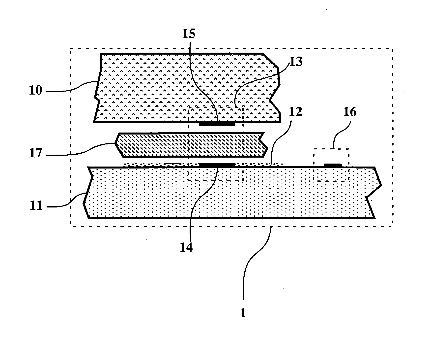
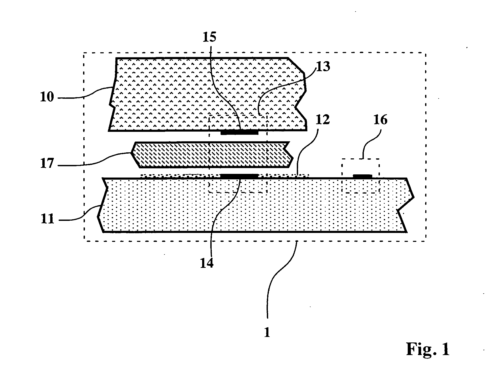
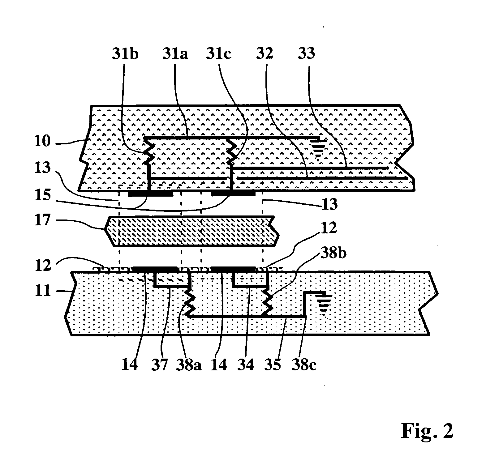
Inspection of the solder joints can be done with thermographic or radiographic techniques, but may be difficult otherwise.
The
package is extremely dense, although heat dissipation can become limiting, but leads must still travel out to the edge and back to
route to other die.
The
package is extremely dense and conceptually trivial, but extremely difficult to manufacture.
However, as the size of a die approaches some economically and technologically feasible limit, the probability that randomly occurring manufacturing defects will produce an unacceptable die rises exponentially in a Poisson distribution.
Since slightly larger die yield at significantly lower rates, this so-called “surface-to-volume” (communication-to-computation) ratio severely constrains fabrication yield, hence cost per functioning die.
The need for multichip technologies arises in large part from this inability to produce arbitrarily large
semiconductor dies with acceptable yield.
Practical limits on die size for a given technology force
system designers to partition large digital systems among multiple dies.
Unfortunately, such partitioning dramatically impacts
system performance since inter-die communication typically inflates packaging costs by tens to many hundreds of percent.
At present, customization generally requires a lengthy (circa six week) logic array masking process, unreliable
laser fusing / breaking of wiring junctions, significant expense in
microfabrication of wiring,
macro-scale (e.g., wire-wrap) assemblages, lack of durability (e.g., hand-wired jury-rigs), or a combination of these.
The number of leads or number of chips within an area may inflate cost by a significant factor in many packaging technologies, such as those using wire-bonds.
Even if a technology avoids scaling as the number of leads or die, if it requires post-
processing steps to form a package, as with solder bump conductive couples, it may still be expensive due to yield losses from handling, amortization of costly test / repair cycles, and of course operating and capital costs.
Runaway wiring density can in principle
choke off the manufacturability of large high performance systems.
A further need for multi-
chip technology arises from the cost and complexity of combining
hybrid materials to
exploit properties of each.
For instance, an arbitrarily large, cheap
silicon CMOS chip would still lack the speed and optical properties of GaAs, while growing one material on the other is inherently more complicated than forming them separately.
A further need arises from the difficulty of package manufacture per se.
Despite the intensive research efforts of the past several years,
present day MCM technologies still have significant problems in terms of cost, performance, design, manufacturability, reliability and reparability, as well as shortcomings with respect to the needs enumerated above.
Present MCM technologies require significant retooling and / or expensive reorientation of existing
integrated circuit (“IC”) fabrication lines.
High volume is needed to realize cost advantages of MCM packaging, but re-implementing an existing production system (for which high volume demand already exists) to utilize MCM technology typically requires extensive system-wide redesign.
Accordingly, the relatively high up-front cost of MCM implementation discourages use of MCM technology for systems where large volume cannot be predicted a priori.
Reparability and die attach yield issues also arise with current MCM technology, principally because of the difficulty in die removal and replacement.
Testing the dies in the MCM before it is fully assembled (and paid for) typically accounts for tens of percent of the delivered MCM cost, due to the need for sacrificial test rigs or time-consuming intermediary connections as well as the cost of compensating for parasitics in order to test at operating speeds.
Making physical contact with microscopic probes or rigs of probes is slow, and exposes the probe points to mechanical forces leading to misalignments, fatigue, and wearing.
Nevertheless, working dies should be selected perfectly before module
assembly, due to the expense (or impossibility) of reworking the module.
Repair methods are very difficult-essentially a tear down and rebuild—and usually require essentially the same elaborate, expensive
assembly technology as used to build the MCM originally.
The difficulties, mechanical constraints and costs of multichip module designs are largely driven by the drawbacks of conductive signalling per se.
If there are (re)movable constituents in the electrical path, there will be exposed surfaces, and unless certain materials (e.g., noble metals) are used on exposed surfaces, conductors may be susceptible to oxidation, although some non-metallic conductors avoid the oxidation problems.
If the entire path is bonded continuously, repair and testing may require physically severing material.
Such breaks introduce
metal fatigue (i.e. increase the likelihood of future failure
modes) and
contamination by conductive dust.
Methods for replacement
pose severe constraints on the design and manufacture of conductively-coupled components in
electronic systems.
Even if these or other approaches were practical in a manufacturing sense, all suffer the series
inductance performance costs of conductive signalling.
State-of-the-art MCM technologies endure much the same performance limitation as current surface mounted IC technologies.
Both families of technology require bonding wires, solder bumps, TAB, or their equivalent, to couple signals conductively between the dies and the substrate (for MCMs) or Level 2 package (for surface mounted ICs), which impose parasitic series
inductance unavoidably.
Parasitic inductance of 50-1000 pH is typical, and introduces significant latency, frequency limitations, and power requirements for signalling off-chip.
While the best currently available MCM technologies reduce the disparity between on-die and off-die communication compared to the conventionally quoted ten-to-one ratio for surface mounted IC technologies, there remain significant penalties associated with inter-die signalling on conventional MCMs.
Current MCM technologies suffer from mechanical and thermal problems, design and fabrication limitations, power costs, complexity, and expense.
It imposes mechanical and cost limitations on the density, number, and arrangement of
signal leads attached to a MCM package or constituent dies in carriers, and generally requires further expense and yet more volume devoted to mounting and interconnecting the leads from chip packages onto Level 2 circuit boards or multichip carrier modules and packaging at all higher levels.
With some MCM technologies, pad bonding locations cannot
overlay active circuits, since applied contact probe pressure or other process steps risk damaging the circuits, so pads occupy real estate at the expense of useful electronic devices.
That wasted real estate costs money (about $10-1000 / square inch).
Since present approaches emphasize placing the pads at the perimeter of the die's active area to minimize wiring lengths (or at the center, to minimize
thermal expansion mismatch), and pad count is often limited by the available perimeter bonding density of the die, many designs are “pad limited,”
wasting chip real estate, and / or “pin-limited,” leading to large, expensive packages.
This variation causes circuitry to produce waveforms of differing spectra, affecting shape and
skew, and differing amplitude, affecting thresholds,
noise susceptibility, power requirements and termination characteristics.
Unreliable waveform spectra and amplitude means that the yield of dies follows a bell curve distribution, with very few able to operate at higher frequencies.
Nearly all leading MCM designs treat power leads and
signal leads the same way at Level 1, which wastes space and loses important opportunities for increasing the density of
signal lines.


