Nanoparticle array and method for producing nanoparticle array and magnetic recording medium

a technology of nanoparticle arrays applied in the field of nanoparticle arrays and methods for producing nanoparticle arrays and magnetic recording mediums, can solve the problems of hardly practical use of techniques, hardly strict control of structure regularity, and high processing cost, so as to achieve efficient manufacturing and efficient formation

Inactive Publication Date: 2005-04-14
SONY CORP
View PDF7 Cites 34 Cited by
  • Summary
  • Abstract
  • Description
  • Claims
  • Application Information

AI Technical Summary

Benefits of technology

According to the present invention, the organic layer in which the adsorption property to the nanoparticles changes due to a partial difference in the molecular structure is provided on the board. The surface of the organic layer undergoes a patterning treatment so that the surface small sections having the adsorption property are formed in the form of the array. Thus, the groups of the nanoparticles can be guided and fixed only to the small sections and the nanoparticle array in which the groups of the nanoparticles are arranged on the board in the form of the array can be efficiently formed.
Further, according to the present invention, the magnetic nanoparticles are respectively fixed on the small sections of the organic layer, so that the magnetic recording medium in which the magnetic nanoparticles are arranged on the board in the form of the array can be efficiently manufactured.

Problems solved by technology

An electron beam or focused ion beam lithography can achieve a nanofabrication such as several nm to several ten nm, however, it requires a high processing cost and takes a long processing time.
Accordingly, these techniques are hardly put to practical use.
Accordingly, the regularity of a structure is hardly strictly controlled to generate turbulence or defects in the arrangement of the nanoscale magnetic material.
In the patterned media, the turbulence or the defects in the arrangement of the magnetic material undesirably cause an error during recording and reproducing data.
However, the patterned media in which the regularity of the mold pattern is precisely reproduced is hardly manufactured owing to a pattern transfer process by a mold press to the resist and a resist pattern transfer process to a magnetic layer by etching.
However, as the method for producing the patterned media, an efficient and accurate nanoscale processing technique has not been yet developed.

Method used


Image

  • Nanoparticle array and method for producing nanoparticle array and magnetic recording medium
  • Nanoparticle array and method for producing nanoparticle array and magnetic recording medium
  • Nanoparticle array and method for producing nanoparticle array and magnetic recording medium

Examples


example 1

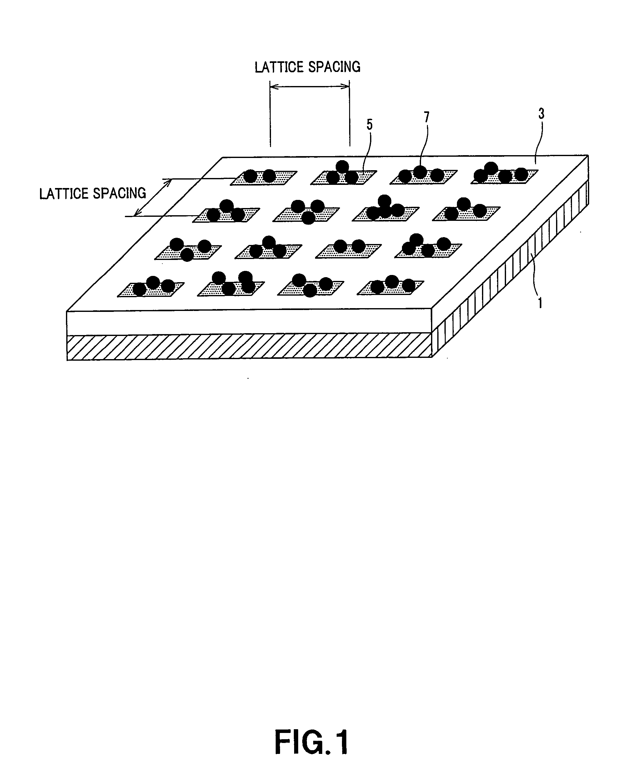
As a board, a p-type Si wafer was used. As a silane compound formed on the board, octadecyl trichlorosilane (CH3(CH2)17SiCl3, OTS) was used. As magnetic nanoparticle dispersed solution, FePt nanoparticle dispersed solution (average particle diameter: 4.4 nm, solvent: hexane, an organic stabilizer: oleylamine) synthesized by applying a method disclosed by Sun et al. Science, 2000, v. 287, p. 1989 was used.

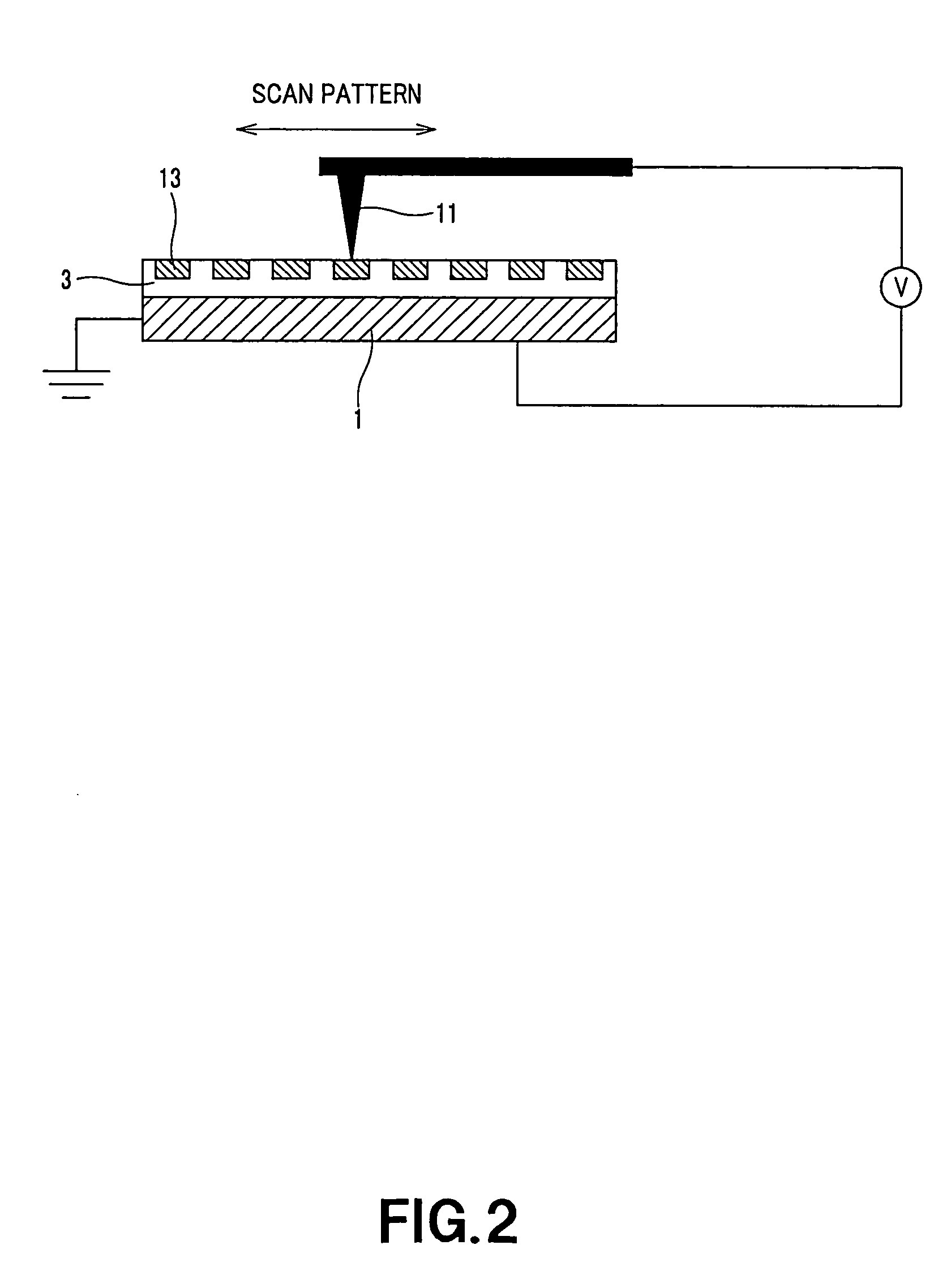
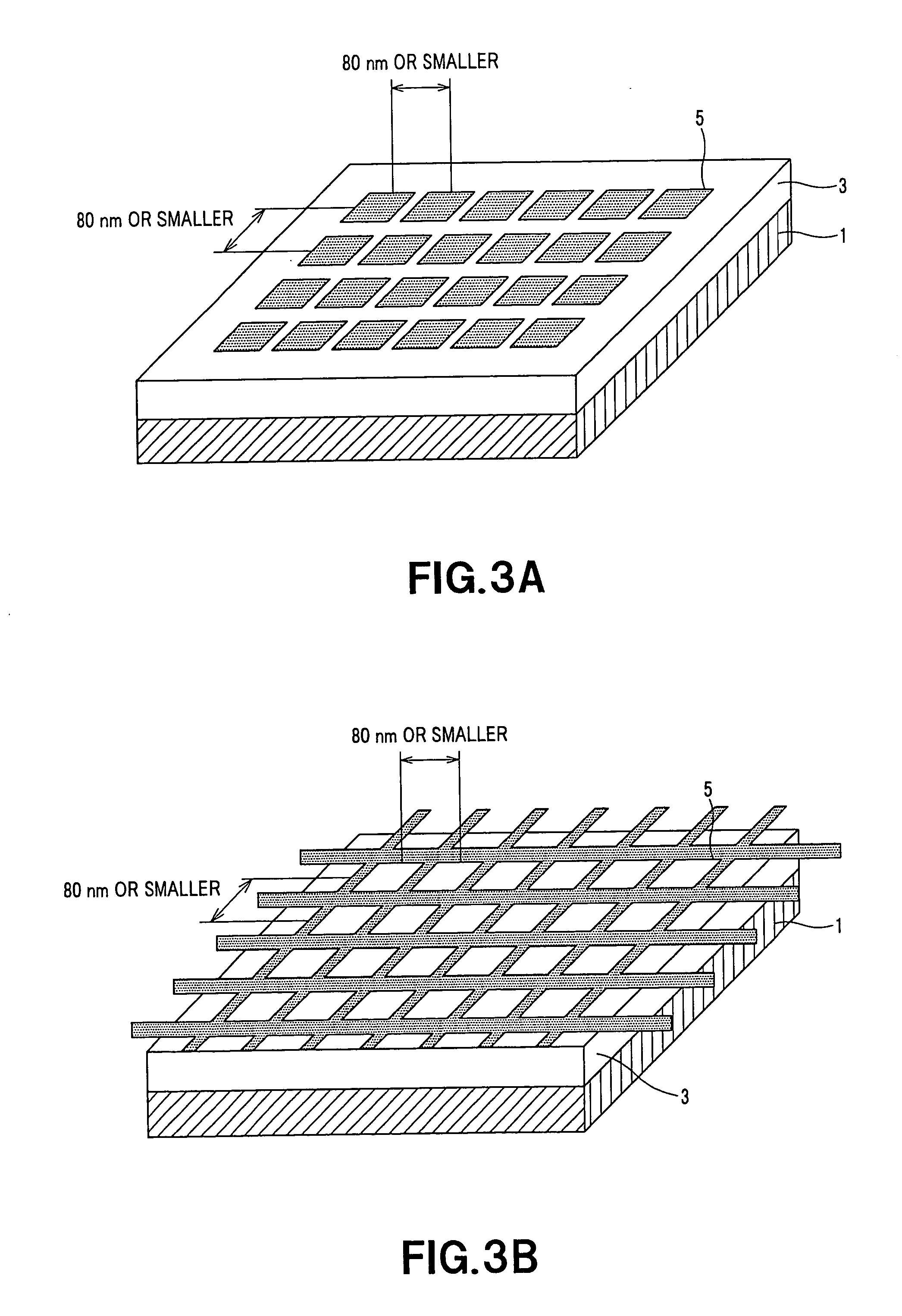
An OTS layer was formed on the board by immersing the board in toluene solution for a prescribed time. A surface patterning and oxidizing treatment was carried out in an atmospheric air by using a scanning probe microscope having a Pt coat probe (end radius of curvature: about 30 nm). As shown in FIG. 6A, the probe scanned at intervals of 70 nm in the direction of an X axis at scanning speed of 1.6 μm / s. As shown in FIG. 6B, when the probe moved in the direction of +Y axis, a positive voltage pulse (voltage: +9.5 V, pulse width: 20 ms, frequency: 25 Hz) was applied to the probe. ...

example 2

As a board, a p-type Si wafer was used. As a silane compound, an APS was used. As magnetic nanoparticle dispersed solution, FePt nanoparticle dispersed solution (average particle diameter: 4.4 nm, solvent: hexane, an organic stabilizer: oleylamine) synthesized by the same method as that of the Example 1 was used.

An APS layer was formed on the board by immersing the board in APS toluene solution for a prescribed time. A surface patterning and oxidizing treatment was carried out by using a scanning probe microscope having a Pt coat probe (end radius of curvature: about 30 nm). While a plurality of lines were traced on the surface of the APS layer, positive voltage of +9.25 V was applied to the probe. As a result of observing an AFM image and an LFM image on the surface of the organic layer after the surface patterning and oxidizing treatment, the AFM image hardly changed from that before the surface patterning and oxidizing treatment. On the other hand, in the LFM image, the format...

example 3

As a board, a thermally oxidized Si wafer (the thickness of an SiO2 layer is 3000 Å) was used. As a silane compound, an OTS was used. As magnetic nanoparticle dispersed solution, FePt nanoparticle dispersed solution (average particle diameter: 3.1 nm, solvent: hexane, an organic stabilizer: oleylamine) synthesized by the same method as that of the Example 1 was used.

An OTS layer was formed on the board by immersing the board in OTS toluene solution for a prescribed time. A surface patterning and oxidizing treatment was carried out by irradiating the surface of the OTS layer with corona (space between electrodes: 1.5 cm, discharge output of 100 W, processing speed: 0.4 mm / sec). When the board that was irradiated with corona was immersed in the FePt nanoparticle dispersed solution for a prescribed time, groups of FePt nanoparticles were selectively fixed only to areas irradiated with corona in single layers. Thus, a magnetic nanoparticle array could be manufactured, because CH3 gro...


PUM

PropertyMeasurementUnit
diameteraaaaaaaaaa
applied voltageaaaaaaaaaa
areaaaaaaaaaaa

Abstract

An organic layer capable of forming surface areas having an adsorption property different from that of a periphery due to the chemical change of a surface functional group is formed on a board. The surface of the organic layer is patterned and oxidized by a scanning probe microscope to form an array pattern in which small sections for adsorbing nanoparticles are arranged. Then, nanoparticle dispersed solution is applied to the organic layer having the array pattern or the organic layer is dipped in the nanoparticle dispersed solution to form a particle layer on the organic layer. At this time, the nanoparticles in the nanoparticle dispersed solution are respectively fixed only onto the small sections. Therefore, a nanoparticle array on which groups of nanoparticles are arranged in an array can be obtained. Thus, the nanoparticle array on which the groups of the nanoscale particles are arranged on the board is efficiently formed

Description

BACKGROUND OF THE INVENTION 1. Field of the Invention The present invention relates to a nanoparticle array in which groups of nanoscale particles are arranged in an array, a method for producing the nanoparticle array and a magnetic recording medium on which groups of magnetic nanoscale particles are arranged in an array. This application claims priority of Japanese Patent Application No. 2003-308754, filed on Sep. 1, 2003, the entirety of which is incorporated by reference herein. 2. Description of the Related Art As the compactness and the high integration of a semiconductor element and the high recording density of a recording medium have progressed, a nanoscale processing technique for producing the element has been required. For instance, in the field of the magnetic recording medium, patterned media in which a nanoscale magnetic material is arranged in the form of a lattice is proposed as a high density magnetic recording media in future (see for instance, a non-Patent D...

Claims


Application Information

Patent Timeline
Patent Type & Authority Applications(United States)
IPC IPC(8): B82B3/00B82B1/00C12M1/34G01N33/53G01Q70/00G01Q70/06G01Q70/14G01Q80/00G11B5/64G11B5/65G11B5/738G11B5/855H01F1/047H01F1/11
CPCB82Y25/00G11B5/855Y10T428/254Y10T428/2995Y10T428/2991
Inventor MIZUNO, MIKIHISASASAKI, YUICHIYU, ANDREW CHAK CHUNGINOUE, MAKOTOTAKAHASHI, MIGAKUTOHJI, KAZUYUKIBALACHANDRAN, JEYADERAN
Owner SONY CORP
Why Eureka
Try Eureka