Rotor-stator apparatus and process for the formation of particles

a technology of rotating shafts and rotating shafts, which is applied in the direction of plant/algae/fungi/lichens ingredients, chemical/physical/physical-chemical stationary reactors, chemical/physical/physical-chemical reactor details, etc., can solve the problems of reducing affecting the production efficiency of the product, so as to reduce the solubility of materials and reduce the size distribution. , the effect of reducing

Inactive Publication Date: 2005-09-15
DAIZIEL SEAN MARK +3
View PDF8 Cites 27 Cited by
  • Summary
  • Abstract
  • Description
  • Claims
  • Application Information

AI Technical Summary

Benefits of technology

[0009] The present invention, however, provides an efficient, simple and easily scaled-up apparatus and process for producing fine particles, wherein a very high mixing intensity can be delivered and controlled over a very short residence time. One advantage of the present invention is that it enables higher volume processes to harness the advantages equivalent to intense mixing delivered by impinging jet systems. Another advantage is that it does not suffer the blockage and complicated alignment limitations of impinging jets.
[0010] Antisolvent crystallization / precipitation, otherwise referred to as drowning out or watering-out, is a widely discussed and industrially used process for causing a substance that has been dissolved in a liquid to precipitate out of the liquid. (See, for example, “Crystallization” by J. W. Mullin, 3rd edition, Butterworth Hienemann 1992, or “Perry's Chemical Engineers' Handbook”, edited by D. W. Green and J. O. Maloney, 6th edition, McGraw-Hill Book Co., NY, 1984). The method involves the addition of a second liquid comprising an anti-solvent to a first liquid comprising a solvent and a substance dissolved in the solvent. The two liquids are miscible and lead to a lowering of solubility of the material to be crystallized in the mixed solvents. As a result, the substance dissolved in the first liquid crystallizes out of the liquid, and can subsequently be isolated if required.
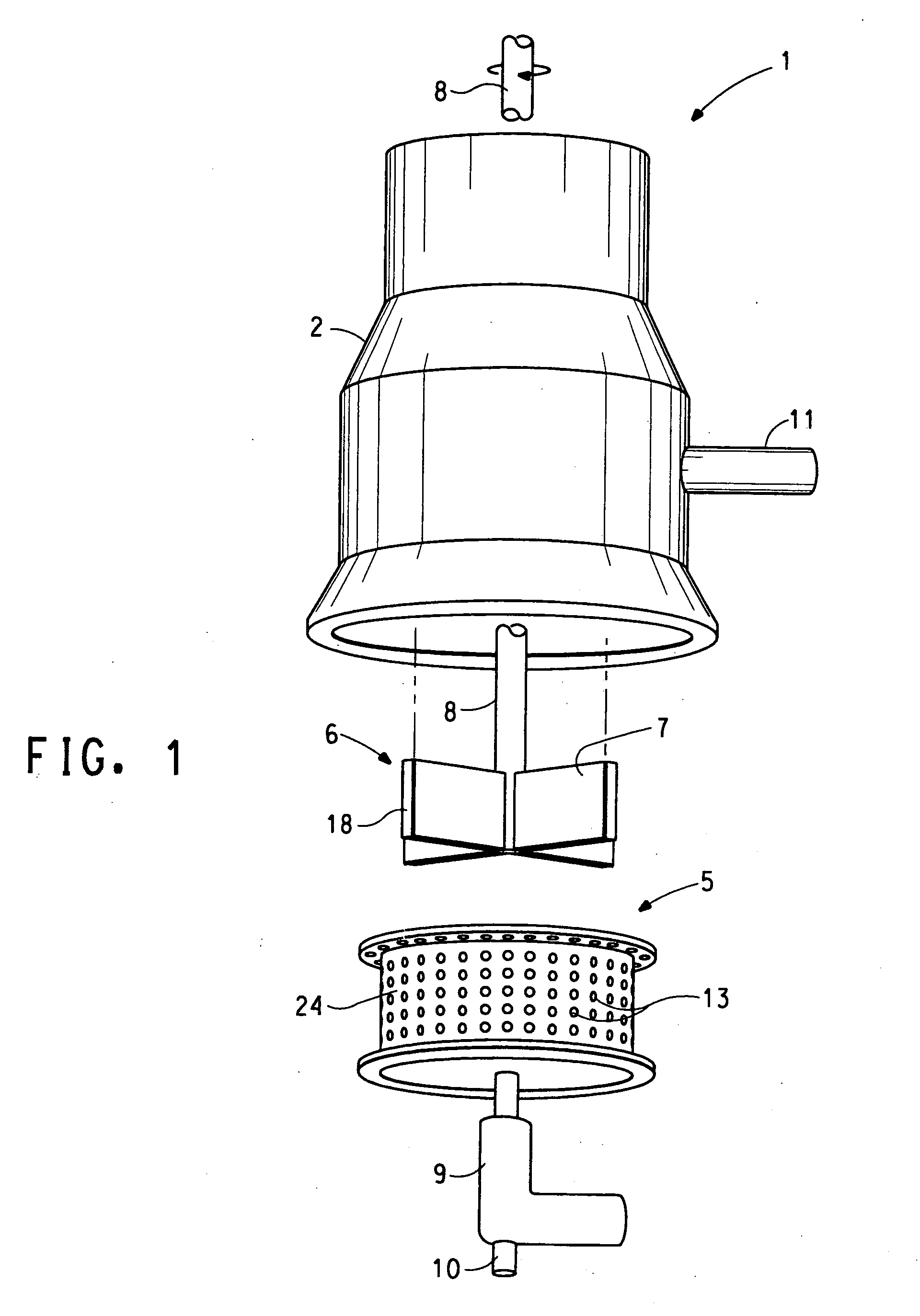
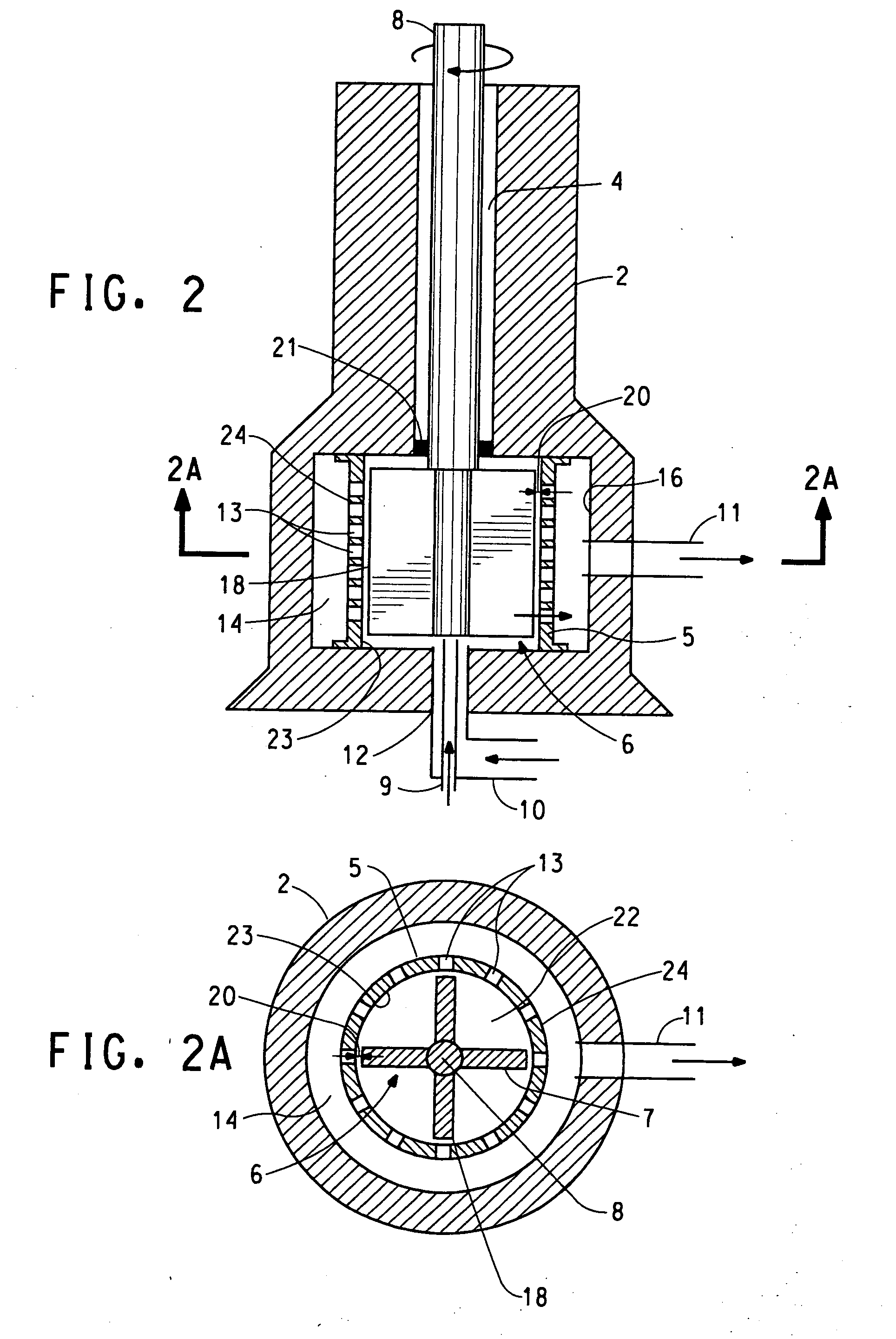
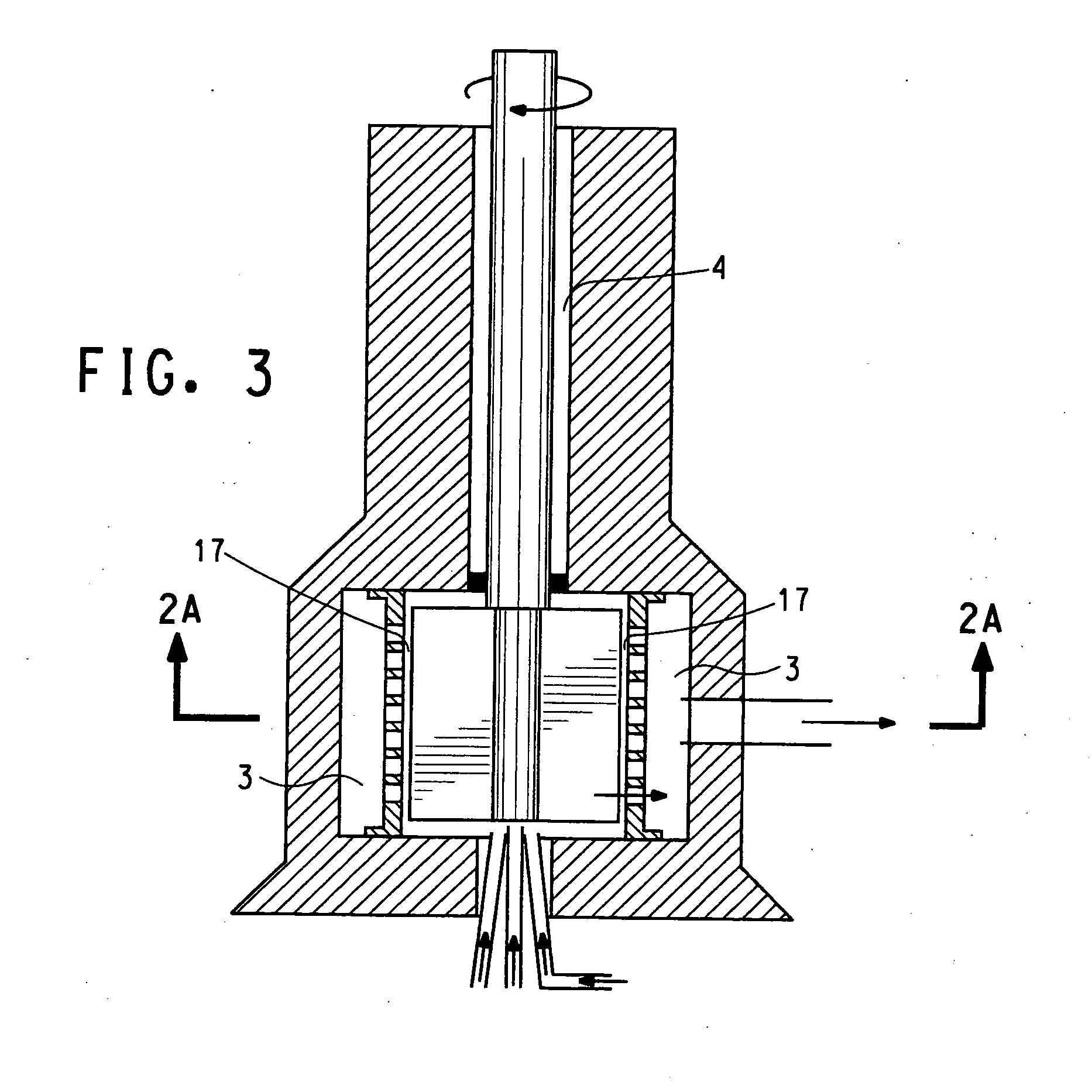
[0011] Currently, rotor-stator mixers are occasionally used as a grinding device following a regular crystallization process. Additionally, rotor-stator mixers have been used, directly, or indirectly after a crystallization unit operation to disperse, attrit or change the shape of previously prepared crystals. Prior to the present invention, rotor-stator mixers had not been utilized as part of a single step crystallization / precipitation process that produces fine (<1.0 micron) or ultra-fine (sub-micron and nano-sized) particles that do not need to be ground in a further post-crystallization / precipitation grinding step.
[0012] Rotor-stator mixers are used in many industries, including the food industry. Food items such as mixed dairy products, mayonnaise, and the like can be produced with these devices.
[0013] Rotor-stator mixers are high-speed stirring devices wherein the rotor portion is a stirrer blade, and the stator portion is a container with openings through which materials pass into an outer housing and then out of the system. The stator is generally sized for close tolerance with the rotor portion. Alignment is not an issue with rotor-stator mixers since the manufacturing techniques to produce them is well established, and the inlet, outlet and stator openings allow for streams larger than those of impinging jets. However, currently available standard rotor-stator mixers provide only one inlet port for fluid streams entering the system.
[0014] The present invention provided herein is a rotor-stator apparatus that allows multiple fluid streams containing different fluids to be fed into the rotor-stator apparatus so that the different fluids do not intimately mix until inside the high shear zone of the mixer. This creates an environment whereby nucleation and crystal / precipitate growth occur over a controlled and very short time period. As a result, the crystals / precipitate produced according to the process and apparatus of the present invention are smaller in size and have a narrower size distribution range than could be obtained by mixing the two liquids in a conventional stirred tank type crystallizer.

Problems solved by technology

Milling, grinding, and crushing, however, impose limitations including contamination of the product by grinding tools, degradation of heat sensitive materials during grinding, lack of brittleness of some solids (e.g., most polymers, proteins, polysaccharides, etc), chemical degradation due to exposure to the atmosphere, long processing times and high-energy consumption.
A large proportion of small molecule pharmaceuticals are poorly soluble in water or gastric fluids.
Conventional batch (or continuous) crystallization processes, if modified to enable a high supersaturation environment to generate fine sized crystals with high surface area, causes a broad size distribution and poor crystal formation.
The conventional batch processes do not provide high quality crystals since such processes simply recirculate the solution in a tank, wherein the solution may or may not pass through the high-shear zone.
Consequently, the products have low purity, high friability and decreased stability and inadequate bioavailability unless further treated.
A slower crystallization process, however, decreases the productivity of the crystallization apparatus and produces large, low surface area particles that require subsequent high intensity milling.
For the reasons stated above, however, post-crystallization milling is an undesirable step in producing fine particles.
As a result, the large-scale production of end-products having high surface area, high chemical purity, and high stability without post-crystallization milling is not obtainable through current crystallization technology.
This crystallization process is designed to produce very fine particles (e.g., approximately 10 μm and less); however, it presents several difficulties and limitations in its utility.
Such high velocities are only practically achievable at low production rates, where very fine bore jets are used.
Since the linear velocity (1-dimension) of the fluid streams and their volumetric flow rate (3-dimensional) do not scale linearly with increasing jet diameter, scale-up of impinging jet apparatus is commonly unsuccessful above rates of several kilograms of product per hour.
Therefore, impinging jet nozzles are only suitable to discharge very fine fluid streams at low production rates.
Secondly, it is very difficult to align, and maintain the alignment of these impinging fluid jet streams.
Again, if the diameter of the jets is increased to accommodate an increased production rate, the dissipation of energy during mixing is less controllable, making scale-up complicated or unsuccessful.
Thirdly, various parts of the impinging jet apparatus used to produce the crystallized particles tend to clog easily with both crystallized, as well as, foreign materials.
Finally, although the impinging jet crystallization process can be utilized to produce fine medicinal substances with particle sizes around 10 μm and less, such a process requires multiple units for larger scale production of fine particles making it a very costly approach to production.
They require additional operators and increased complexity with regulatory requirements on batch records and lot documentation.
Hence impinging jet crystallization / precipitation is not a practical alternative for the larger scale production of fine particles.
However, currently available standard rotor-stator mixers provide only one inlet port for fluid streams entering the system.

Method used


Image

  • Rotor-stator apparatus and process for the formation of particles
  • Rotor-stator apparatus and process for the formation of particles
  • Rotor-stator apparatus and process for the formation of particles

Examples


example 1

Glycine

[0080] Glycine was dissolved in water to prepare 1 L of a 5% (w / w) aqueous solution. The solution was kept at room temperature + / −10 degrees C. This solution was fed to a Silverson Model L4RT-A Rotor-Stator in-line mixing assembly (Silverson Machines, Inc., East Longmeadow, Mass., USA) at a flow rate of 190 mL / min. Simultaneously, anhydrous ethanol (>99%) was co-fed to this rotor-stator, also at 190 mL / min. The rotor-stator was operated at 10,000 rpm. The exit stream of the rotor-stator contained mother liquor and crystals of glycine with an elongated block-like habit, which were observed under a videomicroscope at magnifications up to 1000×. The mean size of these crystals was measured to be 25 μm. A quenching solution of 50% water, 50% ethanol (saturated with dissolved glycine) was used to dissipate residual supersaturation of the exit stream from the rotor-stator.

example 2

Glycine

[0081] The same procedure as in Example 1 was used, except the quenching solution contained 100% ethanol (saturated with glycine). Formed were crystals of sizes ranging from 25 μm to 60 μm and having an interpenetrant (or cruciform) twin habit.

example 3

Glycine

[0082] The same procedure as in Example 1 was used, except where the rotor-stator speed was 5,000 rpm. Formed were block-like crystals where the mean size was 40 μm.


PUM

PropertyMeasurementUnit
particle sizeaaaaaaaaaa

Abstract

The present invention relates to the use of a high intensity, in-line rotor-stator apparatus to produce fine particles via antisolvent, reactive, salting out or rapid cooling precipitation and crystallization.

Description

FIELD OF THE INVENTION [0001] This invention relates to the use of a high intensity, in-line rotor-stator apparatus to produce fine particles via precipitation or crystallization. BACKGROUND OF THE INVENTION [0002] The production of fine particles is used in many applications, such as oral, transdermal, injected or inhaled pharmaceuticals, biopharmaceuticals, nutraceuticals, diagnostic agents, agrochemicals, pigments, food ingredients, food formulations, beverages, fine chemicals, cosmetics, electronic materials, inorganic minerals and metals. Only a few current precipitation and crystallization techniques work reliably to produce fine crystals having a narrow size distribution, and often milling, crushing, or grinding are required, as a post treatment, to reduce the crystallized particles to the desired size and distribution ranges. [0003] Milling, grinding, and crushing, however, impose limitations including contamination of the product by grinding tools, degradation of heat sensi...

Claims


Application Information

Patent Timeline
Patent Type & Authority Applications(United States)
IPC IPC(8): A23J3/16A61K9/14A61K9/16A23J3/08A61K9/72B01D9/00B01D9/02B01F7/00B01F7/16B01F15/02B01J4/00B01J19/00B01J19/18B01J19/26B22F9/24C07C67/52C07C227/42C07C229/08C22B9/05
CPCA23J3/16Y10T117/10B01D9/005B01D9/0054B01F5/104B01F7/008B01F7/164B01F15/0202B01F15/0265B01F2215/0031B01F2215/0032B01F2215/0427B01F2215/0431B01F2215/0481B01J4/001B01J4/002B01J19/006B01J19/0066B01J19/18B01J19/1806B01J19/26B01J2219/00033B01J2219/00768B01J2219/1946C07C67/52C07C227/42C22B9/05A61K9/1688C07C69/86C07C229/08C07C69/157B01F25/52B01F27/272B01F27/812B01F35/711B01F35/71825B01F2101/21B01F2101/22B01D9/02B01D9/00
Inventor DAIZIEL, SEAN MARKGOMMEREN, ERIK HENRICUS JACOBUS CORNELISCALABRESE, RICHARD V.FRIEDMANN, THOMAS E.
Owner DAIZIEL SEAN MARK
Why Eureka
Try Eureka