Method for depositing boron-rich coatings

a technology of boron-rich coatings and boron-rich boron, which is applied in the direction of solid-state diffusion coatings, vacuum evaporation coatings, plasma techniques, etc., can solve the problems of low efficiency of boron depositing

Inactive Publication Date: 2005-09-22
IBADEX
View PDF10 Cites 44 Cited by
  • Summary
  • Abstract
  • Description
  • Claims
  • Application Information

AI Technical Summary

Benefits of technology

[0066] It is further realized that when the companion metal does not readily vaporize, the metal remains present, permitting a gradual thermal decomposition through successive borides from a high boron-to-metal ratio towards the ratio of 4.

Problems solved by technology

Unfortunately, elemental boron is difficult to deposit at a high rate by most commonly used deposition techniques, such as flame spray, plasma spray, or cathodic arc, because as a covalent material, it does not readily conduct electricity (resistivity ˜1014 microohm-cm).
If the former group is utilized in a high temperature deposition system, the boride feedstock may gradually become surface depleted in the metal component which was providing the electrical conductivity.
The silicon is expensive to deposit over large areas and does not conduct electricity well, a problem leading to static charging of surfaces in processing equipment that employs charged particles.
In some processing applications, particularly those for semiconductors, surface contamination from tungsten or tantalum impurities emitted from a nearby heated filament due to evaporation or sputtering is undesirable.
Halverson et al. do not teach the advantages of selecting the ultra-high atomic percent borides that are found solely in Group 3B together with the rare earth elements for their application.
Boron and boride coatings are usually extremely hard.
Magnetron DC sputtering of elemental boron is considered difficult, because the element is not electrically conductive and thus requires the far more inefficient method of RF or pulsed sputtering to frequently discharge the sputtering target.
Similarly, plasma spray of elemental boron has been attempted on numerous occasions, but the high thermal stability of boron combined with the lack of electrical conductivity make the plasma stream very difficult to maintain and thus not commercially practical.
Cathodic arc is another of the high throwing power industrial coating methods that does not perform well with elemental boron.
Electrically insulating elemental boron does not coat well due to charging in the arc chamber, but metal borides behave more like metals during coating.
For example, boron carbide (B4C) is also a poor electrical conductor because it is covalently bonded.

Method used


Image

  • Method for depositing boron-rich coatings
  • Method for depositing boron-rich coatings
  • Method for depositing boron-rich coatings

Examples


example 1

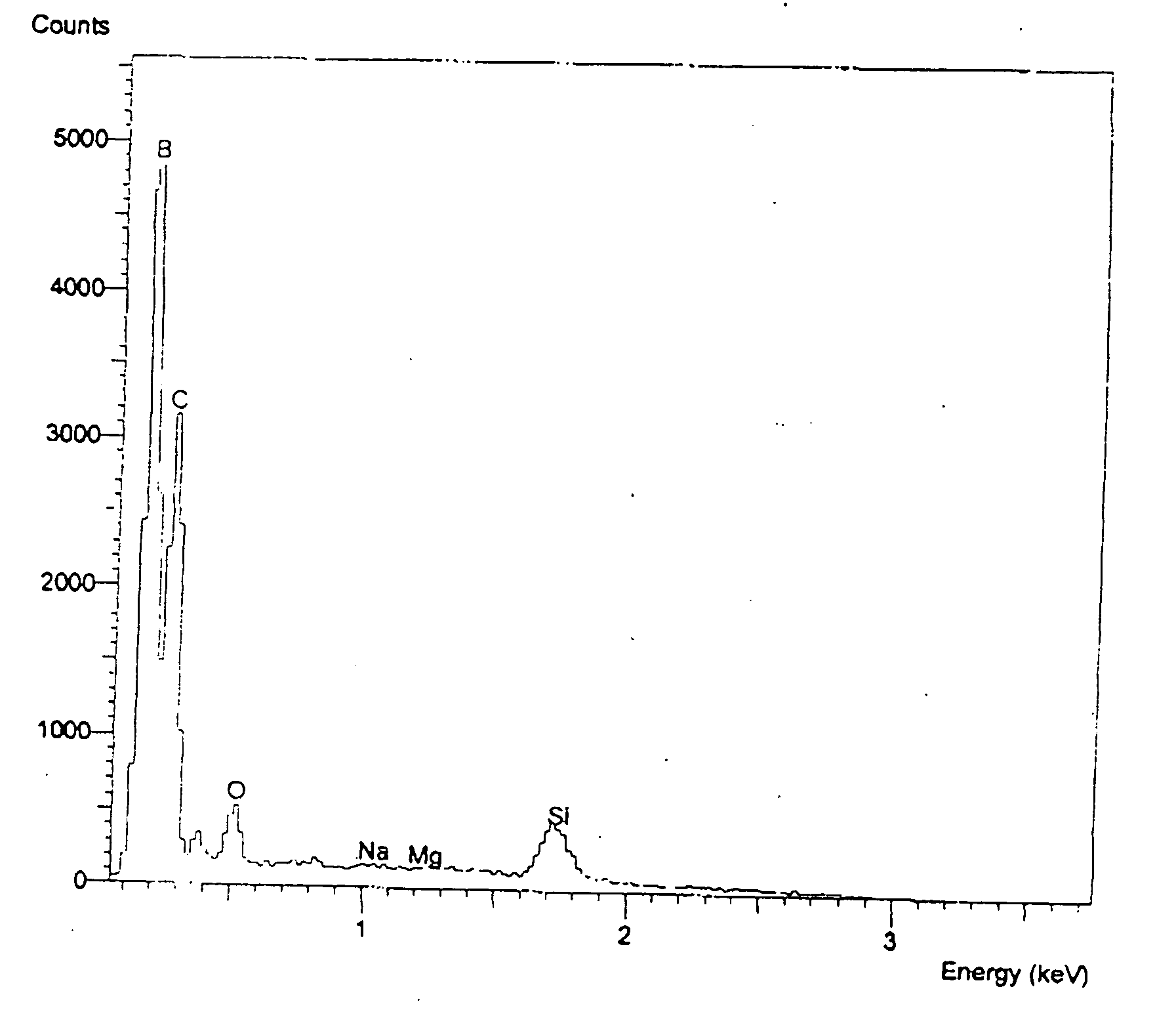
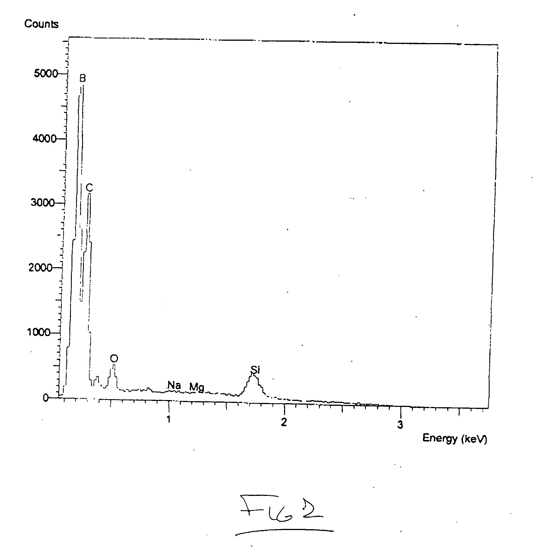
[0074] YB66 powder in the form of typically 50 to 75 micrometer particles has been used as the feedstock in an industrial plasma spray system utilizing argon gas as a carrier. The powder has been observed to spray easily and produce a characteristic granular deposit which can readily be built up to considerable thickness easily exceeding 3 mm. The deposit adheres readily to a wide variety of materials, including aluminum, steel, titanium, carbon, molybdenum, tungsten, tantalum, silicon, alumina, silica, zirconia, boron nitride, porcelain, and an aerogel foam. Good adhesion has been observed for all substrate materials tested. The resultant coating layer is extremely hard and difficult to break. In the case of a carbon substrate, for example, the graphite substrate will typically split or shatter prior to the debonding or failure of the coating. The coating has been rapidly deposited over large surface areas and surfaces with complex shapes using well known plasma spray methods.

example 2

[0075] YB66 has been plasma spray coated onto a tungsten coil filament for use as an electron emitter in an ion source. In addition, other ion source components, including the molybdenum arc chamber walls and graphite electron repeller, have been similarly coated in order to produce an ion source with enhanced boron emission as well as to minimize the output of contaminating atomic species. The tungsten coil filament has been heated to near its normal operating temperature when only the tungsten surface is exposed, and the filament has been observed to produce electrons capable of sustaining the arc discharge of the ion source. The coating was found to melt at the operating temperature of the filament, but the liquid coating did not alter the electron emission properties. The coated filament was found to enhance the boron output of the ion source, and the coating was not observed to detract from the normal filament lifetime, and tungsten contamination of the plasma was significantly...

example 3

[0076] A DC magnetron sputter target has been formed using buildup of a 1.5 mm thick coating of YB66 using plasma spray. The sputter target transferred boron at a rate which was approximately 10 times greater than from RF sputtering. Sputter targets have been made by coating on a backing of graphite, copper and other materials.


PUM

PropertyMeasurementUnit
temperatureaaaaaaaaaa
thicknessaaaaaaaaaa
thickaaaaaaaaaa

Abstract

A method is disclosed for coating substantially pure boron or highly boron-rich borides in a controlled manner. Such a method of coating of boron has a variety of applications, including surface chemical and wear protection, neutron absorption, prevention of impurity emission from heated filaments and ion beams, elimination of metal dust from vacuum systems, boridizing, boron cluster emission, and reactive chemistry. Borides with a boron-to-metal ratio of 20 or more are known to exist and may be used as a feedstock for substantially pure boron coatings for deposition processes requiring feedstock electrical conductivity, and/or enhanced reactivity. While most metal borides coincidentally produce significant metal vapor as a by-product, certain borides of yttrium, holmium, erbium, thulium, terbium, gadolinium, and lutetium have been identified as capable of producing substantially pure boron vapor.

Description

[0001] The present invention relates to a method for producing boron-rich coatings for a variety of uses related to surface protection, sputter targets, electrically conductive layers, semiconductor compatibility, neutron absorption, high temperature bonding, and reactive chemistry, and is a continuation-in-part application of co-pending non-provisional patent application Ser. No. 09 / 560,518, filed Apr. 28, 2000, which is based upon Provisional application Ser. No. 60 / 150,205, filed Aug. 21, 1999, each of which are incorporated herein by reference.FIELD OF INVENTION BACKGROUND OF INVENTION [0002] Elemental boron is a well-known hard, covalent material. It also possesses considerable chemical resistance and is suitable for high temperatures in a vacuum or reducing atmosphere. It is known to impart considerable wear resistance to tooling materials if the boron can be added in sufficient quantity or coated on the workpieces. Unfortunately, elemental boron is difficult to deposit at a h...

Claims


Application Information

Patent Timeline
Patent Type & Authority Applications(United States)
IPC IPC(8): C23C4/10C23C4/12C23C14/06C23C14/32C23C14/34C23C16/00
CPCC23C4/10C23C4/127C23C14/3414C23C14/325C23C14/067C23C4/134
Inventor BECKER, RICHARD C.BUNKER, STEPHEN N.
Owner IBADEX
Why Eureka
Try Eureka